With the advancement of science and technology, mankind is making greater and greater progress in space exploration. The demand for space tasks promotes the update and development of ground measurement and control systems, which are mainly reflected in the fact that the construction period of the monitoring and control stations is getting shorter and shorter; the monitoring, control equipment updating, transformation and addition are becoming more frequent, and the control capacity and links of the monitoring and control stations are increasing. Demand continues to expand. Perfecting the monitoring system of an efficient ground monitoring and control system can improve the work efficiency of the monitoring and control station, improve the utilization of business system equipment, shorten the preparation time for the measurement and control business, and accurately and efficiently complete all the tasks of monitoring and control of satellite services. The precision of satellite control and the prolonged service life of the satellite are of great significance. The main tasks of the monitoring and control station monitoring system in the measurement and control system are: The joint monitoring between the measurement and control equipment is particularly useful for equipment commissioning, system-wide adjustment, and calibration. There is only exchange of measurement and control data between measurement and control equipment, but there is a lack of coordination and cooperation for operating parameters and operation processes. In addition to the business operations, the monitoring system can control and monitor all devices. In these critical stages, the monitoring system is in a “leadership position†and is the initiator and organizer of various operational tasks as well as the monitoring and control of the task process. The existing centralized monitoring system adopts the data acquisition card mode in the hardware structure. It is difficult to expand the system. It is difficult for a single card to adapt to a variety of device interfaces, and there is a bottleneck in data collection. In the software structure, usually focusing on the composition of the ground system at that time, the monitoring screen and operation are relatively fixed. Once other types of equipment are replaced, or the interface of the equipment has changed, the source code needs to be modified to adapt and the maintenance is inconvenient. Affects the stability and reliability of the system. Therefore, we have researched and developed a new monitoring system based on reconfigurable architecture design. Centralized monitoring system The existing monitoring system is usually built together with ground equipment. Generally, a centralized architecture is used, which is composed of an industrial control computer and multiple data collection interface cards, and a monitoring system is composed together with a dedicated monitoring program (see Figure 1). In the centralized system monitoring system, all monitoring and control equipment monitoring information is passed through one or more multi-channel data acquisition cards to collect data to the processing computer. The data processing computer then performs data processing according to the type of equipment and sends the results. The monitoring program displays or submits user processing. The use of a centralized monitoring system has the following problems. ◠All data acquisition and processing are handled by the data processing computer, and the computer processing capability, especially the data collection capability, is very demanding. If the data processing volume is very large or the real-time performance of the data is very demanding, it will cause computer overload and hang-up. This is the biggest problem in the existing centralized monitoring system. ◠Since centralized monitoring systems are mostly dedicated systems, data collection and software processing are combined. Once the system is built, the capacity and mode of the control equipment are basically determined, and the architecture is closed and difficult to expand. ◠The data acquisition interfaces are complex and concentrated, which easily causes mutual interference. ◠Complex wiring and high failure rate. The data acquisition interface of the centralized monitoring system is centralized in a computer. All the data interfaces of the measurement and control equipment distributed in different places of the monitoring and control station are connected to the data acquisition interface card, and various signals such as digital signals and analog signals are distributed together. The wiring is complicated. . Reconfigurable monitoring system design ideas In order to be able to adapt to the new changes, the monitoring system can complete the design and debugging work in the shortest time, support the transformation and addition of equipment within a certain range by adjusting the hardware configuration and software parameter settings of the system, and overcome the disadvantages of the existing systems. . The new system adopts a reconfigurable architecture design, that is, a distributed intelligent data interface unit is used to convert the different physical data interfaces of all measurement and control devices into a unified network interface, and the data is transmitted to the data processing computer through the network. The control software of the monitoring system also adopts the design concept of industrial control configuration. The measurement and control equipment is abstracted into different types of control controls, and the control arrays are assembled to form different channel control links, thereby realizing the reconfigurable design of the entire system. . The architecture of the reconfigurable design monitoring system is shown in Figure 2. Specifically, the system uses a distributed hardware topology and configurable controls. The distribution of hardware topology uses several intelligent data interface units (DIUs) to complete the information exchange with multiple different data interface devices. The intelligent data interface unit can be connected to a monitoring and control device that has a serial port (including RS-232A, RS-422, RS-485), digital interface, and relay interface, and sends the collected data to the data processing computer through the network interface. At the same time, the control instructions of the monitoring system are sent to the measurement and control equipment. The concept of configurable controls is introduced in software design. Different monitoring and control devices can be abstracted into different types of device controls. The configuration database is established through the interface configuration software, and the communication link and communication protocol of the hardware and device of the monitoring and control station are configured and the graphics are used. The software drawing system displays graphs and parameter tables, and completes the support of new monitoring and control equipment by modifying the system configuration and display configuration. In a reconfigurable monitoring system, each measurement and control device such as high power amplifier (HPA), upconverter (CU), field amplifier (LNA), etc. is connected to an intelligent data interface unit or directly connected to a data processing computer via a network. . Each intelligent data interface unit can manage 8-channel measurement and control devices with serial interfaces, 8-channel digital interface measurement and control devices, and 4-channel relay devices. Realization of reconfigurable monitoring system In the reconfigurable monitoring system, the key to realize the hardware reconfigurable is to design the data interface unit DIU with intelligent management and control functions. It can adapt to the measurement and control equipment with different physical interfaces, and can manage and control the measurement and control equipment nearby, and All monitoring and control equipment information is converted to a network interface and forwarded to a data processing computer. 1 Data Interface Unit DIU In order to ensure the stable, reliable and flexible configuration of the system to adapt to different application requirements, the secondary development of the mainstream industrial control product PC104 module is adopted. 1 Data interface unit functions ◠Provides 8-channel full-duplex communication serial ports. The physical interface can be set to RS-232C/RS-485/RS-422A according to the actual system requirements. It can flexibly adapt to the information interface of the controlled device. 2 Data Interface Unit Implementation The hardware design adopts PC104 586 industrial control machine and interface module adapted to industrial control environment. CPU: 300MHz frequency; 32MB DRAM memory; 16 interrupts; 2 RS-232C standard serial ports; 10M/100M BASE-T standard network interface; support mouse/keyboard/floppy/IDE hard disk interface, support IDE Flash electronic disk . Communication card: Supports 8-channel RS-232C/RS-422A/RS-485 standard serial communication, each channel can be set independently. Each channel supports up to 115.2KB/s communication rate. Data Acquisition Card: Supports 8-channel optically isolated DI and 8-channel relay output. Each input can support DC or AC input. The input supports SPDT mode. It has three states: common, normally open, and normally closed, and the conversion rate is 5ms. 3 Embedded Software Design The software design of the data interface unit adopts the embedded system design. We use Linux as the development platform. The work that needs to be completed is: After the design of the data interface unit is completed, as an intelligent management device that does not have input and output peripherals, it manages and controls its own monitoring and control device. 2 configurable software design In the design of monitoring software, the configuration concept of industrial control system is adopted, and different measurement and control devices are abstracted into different types of control device controls, and a system configuration database and a device control database are constructed. By modifying the database parameters, the software system can be flexibly configured. Figure 3 shows the software structure of the monitoring system. 1 device control library All the measurement and control devices are analyzed and classified, and they are abstracted as device controls with different display attributes and control attributes to respectively correspond to the actual measurement and control devices. By operating the device controls, the physical measurement and control devices can be controlled. For example, inverter controls, switch matrix controls, data acquisition interface units, etc. (see Figure 4). Since the main program of the control and monitoring system can be developed separately, it has certain independence. By building a device control library, the reusability and versatility of the entire ground monitoring software can be increased. After years of development and application, we have built a fairly large-scale equipment control library that can basically meet the monitoring requirements of monitoring software for general ground stations. 2 system configuration database In order to ensure the reconfigurability of the system, a system configuration database is designed to save the current type, type, interface, etc. of the device control of the entire system, and the configuration of the system link. The IP addresses of multiple DIUs and the configuration of each channel device are saved. Situation and other information. When the measurement and control equipment of the measurement and control system is changed or the measurement and control equipment is added, the system configuration database can be used to change the system configuration database or add necessary device controls, so that the reconstruction from hardware to software can be realized. 3 Graphical interface production Computer running graphical monitoring interface is the user's control and monitor the monitoring and control station's friendly interface. In order to adapt to the reconfigurable design of the system, we have specially developed a drawing tool that uses a building block to make a device information connection structure and a control interface. Using the drawing tool, the graphic symbol combination of the device control is connected to reflect the current measurement and control device. One or more link diagrams (monitoring screens) configured on the link, and then running monitoring software to open the pre-made link diagram, can realize monitoring and control station equipment monitoring. For similar device controls, devices with the same function may have different access methods, monitoring interface protocols may be different, the form and content of control parameters may also be different, and the display may also have different forms - such as device icons, numerical values Parameters, color blocks, analog graphics, etc., then, they become different device controls, improving the independence of the software system to the device. 3 System Construction Process First of all, the monitoring and control equipment of the monitoring station is analyzed, the functions of system configuration and monitoring screen editing are completed, and the frame design of the real-time monitoring program is completed. After obtaining the monitoring interface control file of the measurement and control device, the system configuration program is used to generate a configuration database, that is, define a device type, a device connection relationship, a device parameter, a device control mode, and a data processing method in the system. Editing and designing monitoring home screens with drawing tools. In the field installation, a data interface unit is installed according to the installation position of the measurement and control device and the interface type of the measurement and control device, and the measurement and control device is connected to the data processing computer through the data interface unit. Use the configuration program to set the communication parameters of each port of the data interface unit and download it to the data interface unit through the network. The physical control device is controlled by the device control of the monitoring screen to verify the correctness of the connection and setting of the system hardware and software. Conclusion We have successfully implemented this kind of monitoring system with a reconfigurable architecture and applied it to the design and implementation of monitoring systems for many satellite service monitoring and control stations, such as the domestic Xinnuo ground station and the Nigerian Abuja ground station, after many years of Engineering practice and operation prove that this architecture is very successful.
Economical Channel type fiberglass flexible Cable support tray Application
Economical Channel type fiberglass flexible Cable support tray:
FRP cable tray is consists of a ventilated or solid bottom contained within longitudinal side members. Provides moderate ventilation with added cable support frequency and with the bottom configuration providing cable support every 4 inches. Available in metal and nonmetallic materials. Generally used with control and instrumentation cables in moderate heat generating applications with short to intermediate support spans of 5 feet to 12 feet. FRP cable tray bottom is available in flat sheet or corrugation that is 3 times stronger and 21 times stiffer than flat sheet bottoms. Corrugated seams between jointing sections eliminate need for bottom seam splices. Load Depths: 3" through 5-1/2" Materials available: Aluminum, hot-dipped galvanized Steel,Stainless Steel or figerglass.
Outdoor Cable Tray,C Channel Cable Tray,Aluminum Alloy C Channel Tray,Channel Type Cable Tray Jiangsu Loncin Electric Equipment Co.,Ltd , https://www.loncincabletray.com
â— Monitoring of ground monitoring and control equipment â— Control and setting of ground measurement and control equipment â— Joint control of ground measurement and control equipment 
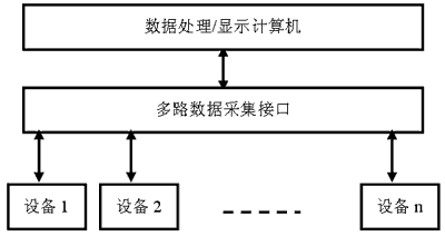
Figure 1 The structure of a centralized monitoring system 
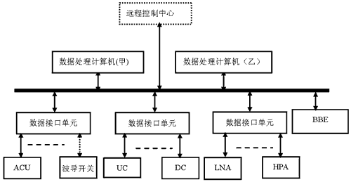
Figure 2 The structure of the reconfigurable monitoring system
â— Provide 8 optically isolated digital inputs and 8 relay output interfaces.
â— Provides 1 way 10/100M adaptive Ethernet data interface with RJ-45 interface.
â— Automatically forward the information of the controlled device to the MCS operation computer through the network.
â— Receives control information from the monitoring computer and automatically forwards it to the specified controlled device.
â— Through the monitoring computer, you can configure the running parameters of the DIU, including the communication speed and the working mode of the DIU.
â— The MCS operation computer can query the DIU's running status information.
â— Make reasonable cuts to Linux through the host. Due to the limited capacity of the embedded system, the huge Linux must be tailored to fit the embedded application.
â— Implement the Linux driver for the electronic disk DOC2000.
â— Design drivers for the extended 8-channel serial communication card.
â— Linux system drivers for designing digital I/O cards.
â— Design data processing applications based on the functions implemented by the data interface unit.
â— Write the stable Linux image to the electronic disk DOC2000. 
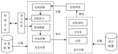
Figure 3 Software structure of ground station monitoring system 
Figure 4 Using Controls as the Main Display Form in the System (Examples)
By configuring the program and running the program, the system framework and the contents of the monitoring are separated. Through the configuration database, the two are organically combined to make the system more flexible and expandable.