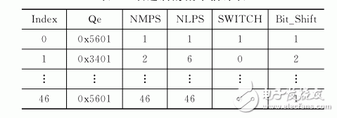
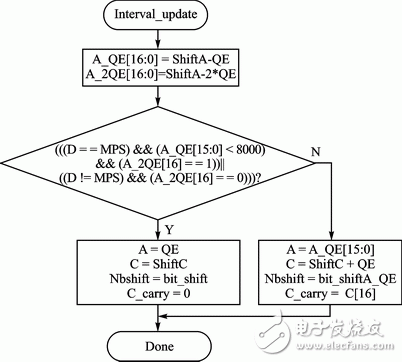
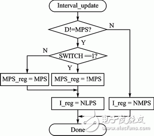
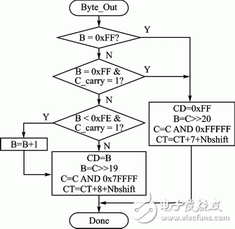
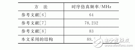
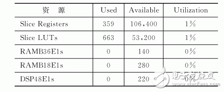
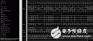
Abstract: MQ coding is a lossless data compression technology that has been adopted by the JPEG2000 standard. Its high complexity has become the speed bottleneck for JPEG2000 system implementation. Based on the analysis of the software flow of MQ coding algorithm, this paper proposes an optimized MQ coding algorithm based on pipeline processing. The algorithm is modularized by the programmable features of Xilinx FPGA, and finally the simulation verification is realized. The results show that the algorithm can achieve a maximum operating clock frequency of 89.8 MHz under the condition of limited resource consumption. The algorithm has certain practical value for the JPEG2000 implementation with strict compression speed. JPEG2000 is a new generation of still image compression standard [1 2]. With the introduction of several innovative technologies, JPEG2000 can provide better compression and more new functions than JPEG. The MQ Arithmetic Encoder is a context-based adaptive binary arithmetic coder. As one of the key technologies of JPEG2000, it has better compression performance than traditional Huffman coding, but frequent renormalization and serial processing also make software implementation. JPEG2000 is very inefficient. With the development of high-performance FPGAs and the increasing demand for large-resolution image compression, JPEG2000 high-speed hardware processing has become inevitable. In order to meet the high-speed processing of MQ coding, experts have studied the implementation of MQ coding hardware and proposed some effective schemes [2, 3, 5]. In this paper, the standard MQ algorithm is combed, and the optimization of MQ coding feedback and loop, interval update condition judgment is proposed, and the MQ code is modularized. A matrix coding FPGA architecture based on pipeline processing is implemented in detail. The MQ encoding belongs to the TIer1 encoding in JPEG2000. The data of the original image wavelet transform is quantized and then divided into a series of bit planes according to the data bit width. The channel is scanned by the bit plane to generate the context; The MQ encoder encodes the context CX with the original data D to generate a compressed code stream CD. Figure 1 is a diagram of MQ coded input/output data. Figure 1 MQ coded input / output data map The MQ encoder workflow is: first look up the context state table (I table) according to the context CX, and find the current probability index value I (CX) and the large probability symbol MPS. Then, according to the current probability index value I(CX), the probability estimate table is searched to obtain Qe, NMPS, NLPS and SWITCH values. Then, according to the probability interval A of the current interval, the encoded character string C, the original data D, and the Qe comprehensive judgment, the updates of A, C, and I are compared. In order to keep A at 0.75~1.5, when A<0.75, the renormalization strategy is adopted, that is, A and C are simultaneously shifted left and doubled to ensure that the probability interval is large enough. Finally, to prevent C-overflow caused by renormalization, the most significant byte of C will be periodically moved to the external buffer, and the output will form a compressed code stream CD. In this paper, the modular pipeline design of the encoding process includes: probability estimation module, coding interval update module, renormalization module and byte output module. 1.1 The probability estimation module is designed in the probability estimation module. The main completion is the probability estimation QE for CX. According to the probability interval A of the current interval, the encoded string C and Qe, it is comprehensively judged whether the original data D belongs to the large probability interval MPS or small. Probability interval LPS. The probability estimation model is a finite state machine [4] with 47 states, each context CX corresponding to one of the states. These 47 states in the FPGA can be implemented by lookup tables, as listed in Table 1. Table 1 Improved probability estimation table The input index of the lookup table is the probability index value I (CX), and the lookup table outputs are Qe, NMPS, NLPS, and SWITCH values, respectively. As mentioned above, when A < 0.75 (0x8000), interval update is required. In the JPEG2000 standard, the interval reforming adopts a loop judgment method, and each time a judgment is performed and then one bit shift operation is performed. Here, the leading zero method can be used to detect how many zeros in the first two digits of the probability interval A, and then shift one time to reduce the shift period. So a Bit_Shift output has been added to the lookup table. 1.2 Coding interval update design The coding interval update is based on the pre-update A and C and the current QE comprehensive judgment. In the JPEG2000 standard, the judgment conditions are more complicated, and the optimization is as shown in Fig. 2. Figure 2 Improved interval update process Among them, ShiftA is the result of A shifting Nbshift bit to the left; ShiftC is the result of C shifting Nbshift bit to the left; Nbshift is the number of one-bit specific left shift; Bit_Shift is the probability estimation lookup table output, and Bit_ShiftA_QE is the height of A_QE 16,15 The number of zeros; C_carry is the most significant byte of the updated C. For Nbshift, it can be understood that when A is selected as QE, the high bit of the QE needs to be shifted to include zero; when A is selected as A_QE, the high bit of A_QE needs to be shifted to include zero. While performing the coding interval update, it is necessary to determine whether the original data D is a large probability or a small probability, and then update the probability index value I(CX). The judgment conditions here are optimized in the JPEG2000 standard, as shown in FIG. Here, NMPS, NLPS and SWITCH are the probability estimation table outputs. The 6-bit width I_reg and the 1-bit bit width MPS_reg are merged as the updated I(CX). The specific I(CX) structure can be found in the reference [1]. Figure 3 Improved interval update process 1.3 Renormalization and Byte Output The design byte output is actually the output of C_carry under certain conditions, that is, when C_carry fills up enough bytes, it is output as CD (or B). The byte output process in the JPEG2000 standard is serially executed and is inefficient. In order to take full advantage of the parallel execution of hardware, we have made some adjustments and optimizations to accelerate the implementation of byte output. The adjusted process is shown in Figure 4. Figure 4 Adjusted byte output flow Here, a dedicated counter CT is set to control the byte output. When renormalization occurs, the probability interval register A shifts Nbshift bit to the left, CT adds Nbshift, and when CT ≥ 20, the MQ arithmetic encoder outputs one byte. . In the process of byte output, if the value in byte buffer B is 0xFF, bit stuffing is required to prevent the propagation of the carry affecting the encoded byte. When the byte output is required, the corresponding byte output operation is performed according to the byte in the byte buffer B and the value of the highest bit C_carry of the register C. Since C_carry is obtained by shifting Nbshift, and Nbshift has a maximum value of 15, that is, C_carry may output 1 or 2 bytes. According to the above system, Xilinx's FPGA chip xc7z020-2clg484 was selected, and each module was implemented and programmed to run on ISE, and the processing speed reached 89.8 MHz. Since the encoder works at a rate of 1 bit per clock, the encoder can operate at speeds up to 89.8 Mb/s, which is far superior to software-implemented MQ encoding. Compared with the references [6] ~ [8], the coding efficiency is greatly improved, and the comparison results are listed in Table 2. Table 2 Comparison of timing results for multiple implementations The FPGA resources occupied by the scheme are listed in Table 3. The resource occupancy is basically the same as the references [6]~[8]. Table 3 FPGA resource usage Figure 5 shows the data from the Modelsim simulation after FPGA implementation. It can be seen from Fig. 5 that some of the initial values ​​of the registers mentioned in this paper can also be seen that the compression byte output condition has been met when CT is equal to 20, and the output B (data_ram_wdata in the simulation diagram) is 0x17. Figure 5 FPGA implementation of post-loop lock phase jitter Conclusion This article introduces the MQ encoding process, detailed algorithm optimization for several of these processes and MQ encoding using FPGA. The results show that the optimized MQ coding can greatly improve the speed of the MQ encoder when using limited resources, and can meet the requirements of the JPEG2000 system. The optimized design adopted in this paper has been verified on the FPGA hardware platform and applied in JPEG2000 compression for aerial large-resolution image processing. FTTH Cable Installation Accessories
The FTTH Installation Accessories Set concludes junction box, fiber wall socket(also named Single family unit rosette, SFU rosette), draw hooks, cable clamp, cable wall bushings, cable glands, cable clips, tail duct, cable wiring duct, nail clip.
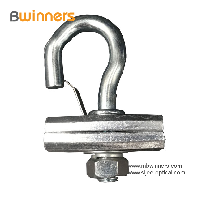
Cable drawing hooks are made of metal stainless steel in accordance with ASTM A307.hanging hardware, hard material, with splint type and C type for option. The conduit box, pipe joint box single gang or double gang are made of PC material, fire retardant.
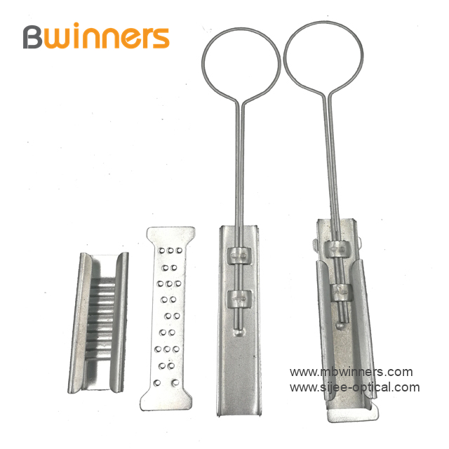
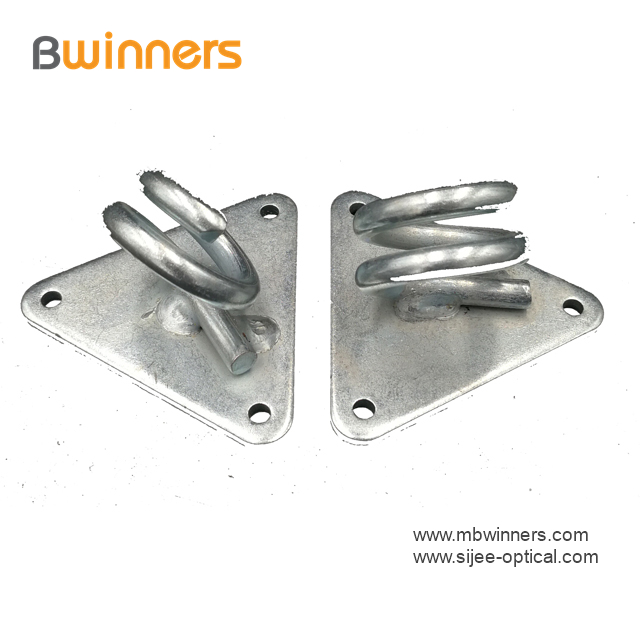
Drop Wire Hanging Holder,Drop Wire Hanging Holder,Cable Pole Clamp,Cable Fitting Clamp are available.
Drop Wire Hanging Holder,Drop Wire Hanging Holder,Cable Pole Clamp,Cable Fitting Clamp Sijee Optical Communication Technology Co.,Ltd , https://www.sijee-optical.com

Applications:
Span Clamp is attached to the messenger wire at mid span to hold the p-clamps with drop wires
Telecommunications subscriber loop
Fiber to the home (FTTH)
LAN/WAN
CATV
