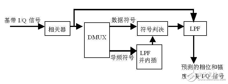
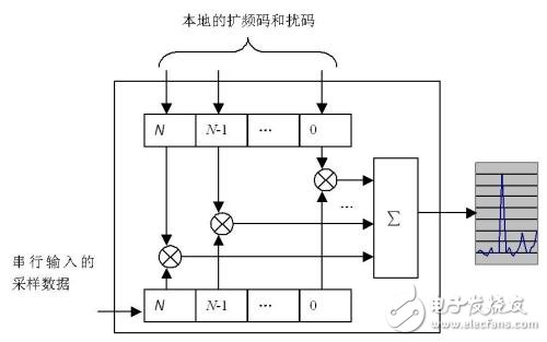
A RAKE receiver is a final receiver that separates multipath signals and efficiently combines the energy of multipath signals. RAKE receiving technology is an important technology in the third generation CDMA mobile communication system. In the CDMA mobile communication system, due to the wide signal bandwidth, there are complex multipath radio signals, and communication is affected by multipath fading. The RAKE receiving technology is actually a multipath diversity receiving technology, which can distinguish fine multipath signals in time, and weight-modulate these resolved multipath signals to form a strengthened signal. Since the transversal filter in the receiver has a saw-like tap like a dice, the receiver is called a RAKE receiver. In a CDMA spread spectrum system, the channel bandwidth is much larger than the flat fading bandwidth of the channel. Different from traditional modulation techniques, an equalization algorithm is needed to eliminate inter-symbol interference between adjacent symbols. The CDMA spreading code requires good autocorrelation properties when selected. Thus, the delay spread that occurs in the wireless channel can be seen as just a retransmission of the transmitted signal. If the delays of these multipath signals exceed one chip length, they will be considered as uncorrelated noise by the CDMA receiver and no longer need to be equalized. Since the multipath signal contains information that can be utilized, the CDMA receiver can improve the signal to noise ratio of the received signal by combining the multipath signals. In fact, what the RAKE receiver does is to receive each of the multipath signals through multiple correlation detectors and combine them. The picture shows a RAKE receiver, which is a classic diversity receiver designed for CDMA systems. The theoretical basis is that when the propagation delay exceeds one chip period, the multipath signals can actually be regarded as irrelevant. of. The correlator with DLL is a demodulation correlator with a phase-locked phase-locked loop. The early and late gates and the demodulation correlator differ by ±1/2 (or 1/4) chips, respectively. The subtraction of the correlation result of the gate sooner or later can be used to adjust the code phase. The performance of the delay loop depends on the loop bandwidth. Due to the effects of fast fading and noise in the channel, the phase of the actual received path has a large change from the phase of the original transmitted signal. Therefore, the phase rotation is performed according to the result of the channel estimation before the combination, in the actual CDMA system. Channel estimation is done based on the pilot symbols carried in the transmitted signal. According to whether the transmitted signal carries the continuous pilot, phase prediction based on continuous pilot and phase prediction method based on decision feedback technique may be respectively used. (1) based on continuous pilot signals The channel estimation method using the discontinuous pilot condition of the decision feedback technique LPF is a low-pass filter that filters out noise in the channel estimation result, and its bandwidth is generally higher than the fading rate of the channel. When discontinuous pilots are used, the interpolation technique is used to perform channel estimation in the pilot gap. When the decision feedback technique is used, the data symbols in the channel are first hardly judged, and the determined result is used as a priori information (similar to pilot). Performing complete channel estimation and obtaining better channel estimation results through low-pass filtering. The disadvantage of this method is that the accuracy of channel estimation is greatly reduced when the noise is relatively large due to nonlinear and non-causal prediction techniques. A large decoding delay is introduced. The effect of the delay estimation is to obtain the signal energy distribution at different time delay positions by the matched filter, identify the multipath positions with larger energy, and distribute their time amounts to different receiving paths of the RAKE receiver. The matching accuracy of the matched filter can reach 1/4 to 1/2 chips, and the interval of different receiving paths of the RAKE receiver is one chip. In the actual implementation, if the update rate of the delay estimation is fast (such as tens of ms), the phase-locked loop of the gate can be eliminated. (2) The basic structure of the matched filter The main component of the delay estimation is the matched filter. The function of the matched filter is to correlate the input data with the local codewords of different phases to obtain the correlation energy of the phase of different codewords. When the serial input sample data and the local spread code and the scrambling code have the same phase, the correlation capability is the largest, and there is a maximum value at the filter output. Based on the correlation energy, the delay estimator can obtain the multipath arrival time amount. From an implementation perspective, the processing of the RAKE receiver includes a chip level and a symbol level, and the processing at the chip level has a correlator, a local code generator, and a matched filter. Symbol level processing includes channel estimation, phase rotation, and merge addition. Chip-level processing is typically implemented in ASIC devices, while symbol-level processing is implemented in DSP. Although the implementation method and function of the RAKE receiver between the mobile station and the base station are different, the principle is exactly the same. For multiple receive antenna diversity reception, the multipath received by multiple receive antennas can be processed in the same way as above. The RAKE receiver can receive both multipath from the same antenna and multipath from different antennas. From the perspective of RAKE reception, the two types of diversity are not fundamentally different. However, in implementation, the control of the branching is performed due to the data of the plurality of antennas, which increases the complexity of the baseband processing. SHAOXING COLORBEE PLASTIC CO.,LTD , https://www.colorbeephoto.com