With the development of modern automobile industry and electronic technology, functional electronic systems such as vehicle navigation, communication, mobile office, multimedia entertainment, security assisted driving and remote fault diagnosis can form an in-vehicle information network system through network technology networking. The future automotive instrumentation system is developing in the direction of an integrated, intelligent and fully graphical vehicle information system platform. This article refers to the address: http:// Overview of Vehicle Information System Platform The future in-vehicle information system platform will completely surpass the existing functions of traditional automotive instrumentation. The main functions of the system include: full graphic digital instrument, GPS navigation, car multimedia entertainment, vehicle status display, remote fault diagnosis, wireless communication, network office , information processing, intelligent traffic assisted driving and more. The future in-vehicle information platform is a high-end integrated information display platform integrating human, vehicle and environment, integrating technology of electronics, communication, network and embedded. The main functions of the in-vehicle information system platform should at least include the following aspects: the meter shows It mainly contains all the functions of traditional instruments. With a liquid crystal display (LCD) as a display terminal, a large amount of complicated information required can be displayed on the LCD screen in a graphical manner, flexibly and accurately. The basic requirements are high-brightness graphics, high real-time response, and the ability to receive signals from the CAN bus and sensors. Vehicle monitoring and remote fault diagnosis Through the collected information, the vehicle information is diagnosed and analyzed, the performance and condition of the vehicle are monitored more intelligently, and the user is prompted. At the same time, the diagnostic analysis data and the diagnostic service center are transmitted in real time through the GPRS module of the vehicle information platform. Through the external GPS module and communication module, and through the monitoring center, vehicle anti-theft monitoring and remote control. wireless online By covering the national GSM/CDMA/GPRS signal, wireless Internet access anytime, anywhere, the maximum rate can reach 153.6Kbps, which can realize E-Mail, FTP, online chat, browsing information, online games, picture download, mobile office, e-commerce and other networks. Features. Fast speed, stable performance, safe and reliable. Navigation information Achieve complete navigation. With GPS global positioning system, users can locate and continuously locate in any corner of the world. In addition to providing functions such as autonomous navigation, information inquiry, optimal driving path calculation, track recording and playback, it also provides traffic congestion prediction. Advanced features such as parking lot parking guides, real-time updates of map data that can be connected to the network. The display of the navigation information system is limited to a local area and should not affect the simultaneous display of the instrument system. Car phone With CDMA wireless communication or VOIP network phone, the car hands-free and wireless headset seamlessly switch to ensure the driving safety of the owner during the call. Car entertainment The in-vehicle entertainment system has evolved from a previous radio and a cassette player or CD player to a system that can communicate with other vehicles through a variety of entertainment and information. More demanding than many other audio/video applications, such as home appliances for A/V systems. To meet people's requirements for car entertainment and comfort, satellite digital broadcast reception, car digital TV reception, CD/DVD playback, etc., and multimedia playback functions such as MP3/MP4/IPOD/USB. Audio and video files can be downloaded wirelessly, completely eliminating the hassle of using discs. The front center console or headrest-style true color display and high-fidelity car audio provide users with professional-grade audio-visual enjoyment. Auxiliary safe driving Mainly include: driver fatigue monitoring, front and rear ranging radar systems, collision analysis, brake control, safety alarm system and auxiliary rear view system. The driver's monitor is placed under the steering wheel to capture the driver's face and automatically analyze the eyelid opening. After analysis, if there is fatigue driving, it will automatically alarm; at the same time, the front range radar and the rear range The radar system automatically measures the front and rear distances and sends this information to the collision analysis unit. If there is a danger of collision, an alarm will be issued, and the drive motor of the seat belt will be automatically braked or controlled, so that the occupant is in an optimally designed position before the collision occurs, so that the consequences of the accident are minimized. Its auxiliary rear view function is mainly through the reverse shift, you can see the full color image behind the car from the high-definition LCD display, and the auxiliary rear view and rear view camera have the functions of anti-glare and night vision, which is convenient for the owner to ensure the night. The safety of reversing. Vehicle information collection system for new intelligent transportation system Obtaining real-time and reliable traffic information has always been a bottleneck problem in the development of intelligent transportation systems. Establishing an intelligent traffic vehicle information collection system can provide good auxiliary tests for the study of driving behavior characteristics, traffic data collection, and field testing in intelligent transportation systems. The verification platform can also be used as an auxiliary detection means to provide strong technical support for the construction and development of multi-functional experimental vehicles of intelligent transportation systems in China, thus accelerating the research and development of related technologies of intelligent transportation systems in China. The vehicle information platform includes many aspects of technology. The following briefly introduces several key technologies involved as follows: Telematics system based on embedded technology Telematics is a composite word composed of communication and information science, commonly referred to as in-vehicle telematics. It combines automotive manufacturing and IT technologies, including computers, mobile communications, digital broadcasting, etc.; at the same time, it relies on the "3S" of ITS to rapidly develop into a new business that integrates technologies and services. Telematics connects the vehicle terminal to the service center via a wireless channel to form a communication link that provides information services. Through the terminal system installed in the car, analyze various conditions occurring inside and outside the car, collect various information necessary for driving and driving, and perform a series of necessary controls to provide convenience and safety for the driver and passengers. entertainment. The technical characteristics of Telamatics fully demonstrate the integration of modern technology. It uses five main technologies: satellite positioning technology (GPS); wireless access technology; cellular communication technology (2G/3G); narrowband network technology (DSRC) for dedicated short-range communication; digital broadcasting and multimedia broadcasting technology (DMB), fusion Become the main function of 4 categories: (1) Ground navigation based on satellite positioning technology (GPS+GIS). Guide the vehicle to the destination with the best route according to the state of the road. (2) Intelligent transportation based on ITS digital broadcasting (GPS+GIS+LBS+CDMB). A typical application is the pilot of real-time conditions on the road. It is different from geographic information-based navigation. On the basis of navigation, it uses the Location Based Services (LBS) generated on the road to guide the vehicle not only to select the best geographical route, but also to select the shortest time required. Optimized routing. Through the real-time multimedia information of the road surface conditions published by the ITS Information Center, the results of voice, analysis and measurement processing are transmitted in the form of broadcast, and the geographical data of remote sensing measurement is synthesized into the pilot map guiding the real-time driving in the form of data, promptly reminding the driver to avoid the traffic. Blocks or unexpected sections give the best modified driving route to reach the destination in the shortest possible time. (3) Remote information service based on wireless mobile communication technology (2G/3G+DSRC+WLAN). On the one hand, it builds a piconet in the car in the form of WLAN, and realizes networked communication and information service with a common information platform, which is basically consistent with the functions of mobile communication and wireless Internet access; on the other hand, RFID tags and readers, and then RFID In the DSRC Internet Service Center, the information of the engine temperature, exhaust gas, tires, gasoline and driving conditions collected by the ECU is sent to the service station of the service center in the information platform mode to realize remote vehicle fault diagnosis and help; The billing information and the service cost information are sent to the settlement center of the service center. The service center can analyze and judge whether the vehicle has any faults, whether there is any possible out-of-control or theft, and can inform the driver in time. Can command the car to slow down, stop running or fail to start. At the same time, accurate accounting and automatic charging. (4) On-board cultural entertainment based on digital broadcasting technology (CDMB-T/CMMB+ITS). It not only displays TV programs, road conditions, MTV, video games, etc. in the car, but also displays and manages personal program information resources (data broadcasting), and downloads geography, landforms, maps, etc., and displays them at any time via broadcast broadband. Internet information such as E-Mail. The Telematics device is usually an embedded system, and it has no difference in software and hardware system architecture design from ordinary embedded systems. In the PC industry, the choice of computing platform, that is, the choice of processor and its related reference design, is quite limited, no matter what kind of Intel or AMD, but the hardware of the embedded system needs to face each Different needs. The right selection and architecture must meet customer and product requirements. This is a very important thing. At present, a telematics system based on embedded technology is designed. The hardware system adopts an efficient and flexible ARM+FPGA architecture. ARM (Advanced RISC Machine) is a high-performance 32-bit reduced instruction set. The device mainly performs external data collection, sorting, analysis, storage and other functions. The FPGA (Field? Programmable? Gate? Array) is a field programmable gate array, which is mainly used for display of the user interface. A typical application example of this hardware architecture is the intelligent in-vehicle information platform launched by Xilinx and Microsoft Automotive Business Unit. It is also known as the Microsoft Telematics Platform (Microsoft Telematics Platform), which is cleverly combined with Internet commands through voice commands. Communication and control is a hub for integrating various mobile devices and transmitting information over the Internet and wireless networks. Microsoft's automotive business unit and Xilinx have created a hardware platform that delivers these benefits at a low cost, facilitating the development of simpler, more reliable and affordable solutions for drivers around the world. For any hardware platform, flexibility and scalability are critical to the success of the architecture, whether it's a basic system or a high-performance, high-end telematics system. With this in mind, Microsoft has developed a truly customizable and scalable automotive standard in-vehicle information processing platform. The platform integrates an ARM 9-based microcontroller that supports more than 32MB of flash/32MB of DRAM and includes integrated GPS Bluetooth and a GSM phone module. External vehicle connections include a CAN network interface and protected analog and digital I/O for LED driver and button input. The basic architecture of the platform is shown in Figure 1. Microsoft takes advantage of the flexibility and high integration capabilities of FPGA technology. The platform uses a Spartan3 XC3S400 FPGA for multiple independent purposes, such as GSM telephony interface, vehicle interface (CAN controller and K-line), and sophisticated audio signal conditioning and routing functions (see Figure 2). . The high level of integration provided by FPGAs also has the advantage of including multiple buses, interfaces, and clocks in a single device, making design that utilizes EMI easy to manage. In addition, reducing component count and board space will reduce production costs and achieve higher manufacturing quality, which are important factors in any automotive design. Knowing the essence of vehicle development and the many different vehicle interfaces available today, Microsoft deliberately designed a flexible solution that allows for rapid modification of the back-end vehicle interface without affecting the underlying architecture and system performance. For example, in the future it will be possible to tune the FPGA solution to meet the needs of end applications with automotive buses such as MOST, IDB-1394 or other digital vehicle networks. Vehicle information platform display system The vehicle information platform generally uses a liquid crystal display (LCD) as a display terminal, and a large amount of complicated information required can be displayed on the LCD screen in a graphical manner, flexibly and accurately. The cross section of the LCD is much like a stack of layers of sandwiches. The outermost layer on each side is a transparent glass substrate with a thin film transistor in the middle of the glass substrate. The color filter and liquid crystal layer can display the most basic colors of red, blue and green. Usually, there are lights behind the LCD to display the picture. Generally, as long as the current does not change, the liquid crystal is in an amorphous state. At this time, the liquid crystal allows any light to pass. After the liquid crystal layer is affected by the voltage change, the liquid crystal allows only a certain amount of light to pass. The angle of reflection of the light is controlled according to the liquid crystal. When the supply voltage of the liquid crystal changes, the liquid crystal is deformed, and thus the angle of refraction of the light is different, thereby causing a change in color. Compared with CRT displays, the advantage is that the LCD display consumes less power; it does not generate electromagnetic radiation like CRT; it does not produce flicker like CRT; it is very small in size, light in weight, and large in visible area. These features make the LCD screen particularly suitable for use on in-vehicle information platforms. In-vehicle information platform often needs a large amount of information to be displayed, but the LCD display size and the installation space in the car are limited. Therefore, one-screen multi-display or multi-screen display technology is often used to display automobile instrument information, vehicle body condition information, navigation information, and multimedia information. Information such as rear view and rear view are displayed on the LCD screen. Figure 3 is an example of a multi-screen display technology: In recent years, as customers' demand for “head-up display†(HUD) has gradually increased, major manufacturers have also sought quality control systems suitable for HUD. The system not only guarantees a high degree of safety, but also adapts to the speed of the production line. The HUD Heads Up Display, also known as the head-up display system, is an integrated electronic display device consisting of electronic components, display components, controllers, and high-voltage power supplies. It can project important information through optical components onto the light/electric display on the windshield directly in front of the steering wheel, so that the driver can see important information without having to bow his head. The role of this display system is to improve the safety of the car. Nowadays, the head-up display system has developed rapidly and has been applied to high-end cars, as shown in Figure 4, which is the HUD system installed on the BMW X5 X6 series. The car navigation system includes three parts: car navigation terminal, digital map and navigation platform. The digital map and navigation platform are all in the background service, and the software and hardware environment can be free from any restrictions; the car navigation terminal (VNT) is not the case, because its working environment is harsh, the soft and hard conditions are limited, and it brings great development work. challenge. The navigation platform is responsible for collecting, analyzing, and processing (including data fusion) various types of road traffic geographic information collected by the traffic information collection system, and transmitting it to a special node and vehicle through a communication system (such as radio paging). The traffic information collection system includes a fixed traffic information detection system (video, microwave, coil, laser and other traffic detectors) and a dynamic traffic detector (taking a taxi as an example, it is equipped with a car navigation system, and itself can also be used as a A traffic information detector that communicates with its center by a trunking communication network). The communication system includes wired and wireless communication, which is responsible for information exchange between the vehicle and the navigation platform (integrated information platform, traffic control center), so as to achieve information exchange between the vehicle and the road network. The VNS is mainly composed of a vehicle positioning module, a multimedia navigation electronic map, an in-vehicle communication module, and other in-vehicle devices. The multimedia navigation electronic map provides the system with various traffic geographic information such as geographic features, road location, traffic rules, infrastructure, and the like. It is based on GIS operations and query electronic maps, including the ability to provide electronic map display, browsing, zooming and information retrieval services. The vehicle positioning module is composed of a positioning sensor and a data processor, and can provide real-time and continuous vehicle position information. In order to make the positioning information more accurate on the electronic map, map matching is needed. The map match compares the location of the location output with the road location information provided by the map database and determines the current travel segment of the vehicle and the exact location in the road segment through an appropriate pattern matching and identification process. If the accuracy of the electronic map is very high, the overall positioning accuracy of the system will be improved and a reliable guarantee for path guidance. The car navigation terminal is equipped with an operating system, a multimedia electronic map, a geographic information system and related software systems. They are responsible for receiving and processing information, planning the route, helping the driver to select the appropriate travel route before or during the trip, and planning for future results needs to be implemented by the route guidance function. Path guidance is a process that helps the driver to travel along a predetermined route to successfully reach the destination. It generates appropriate real-time driving instructions such as voice prompts, graphic displays, etc. based on the road information in the map database and the current vehicle position provided by the positioning module and the map module. In addition, in the car navigation terminal, the human-computer interaction module composed of the display, the controller and the related software system is an important component. It provides an interactive interface between the user and the vehicle terminal. The user inputs the operation instructions such as map display, information query and path planning into the terminal, and the controller also passes the electronic vehicle map as the background of the vehicle position and the optimal path planning result. The information required by the user, such as the real-time driving guidance command, is expressed in a multimedia manner such as voice prompts and visual graphics. Map matching and path planning are the two most important technologies of vehicle navigation terminal (VNT). A good map matching method can greatly improve the positioning accuracy of the system. The advantages and disadvantages of the path planning algorithm directly affect the navigation function of the product. Multimedia information and entertainment system based on vehicle network technology#e# Multimedia information and entertainment system based on vehicle network technology For users who purchase a car with a car network, the biggest benefit is the ability to share information across the network. The car can transmit video, audio and data content to passengers via the in-vehicle network, through which users can access content on the home network using the Internet or subscription services. With the advent of the 3G era, there is an urgent need to establish a multimedia security infotainment system that can provide these services and transmit such content. ·Design of multimedia transmission system The media and information networks are mainly for telematics, multimedia, navigation systems, etc. The transmission rate of network protocols is between 250Kb/s and 400 Mb/s. To realize the function of multimedia data transmission in the in-vehicle system, it is urgent to solve the following four problems: (1) These new applications require that the frequency band of the network be an order of magnitude greater than the bandwidth of the network on existing vehicles, such as Controller Area Network (CAN) and Local Area Network (LIN). (2) The nature of video and audio content determines that they must be considered acceptable to the user when publishing content. Audio delays or display pixels that appear to be erroneous on the display are unbearable. (3) Since the content is published in digital form, the designer must be very concerned about how to ensure the security of the content. (4) Because the virus may be inadvertently brought in when connected to the client's peripherals, it is necessary to ensure the security of the network to prevent virus intrusion. With the development of the embedded product market, there are some problems in the system, and many emerging technologies compete to become the mainstream solution. In summary, there are four main technologies: (1) CAN technology. CAN technology is a technology currently in use, and the new version of CAN has increased bandwidth. But this agreement does not support high quality services. (2) Firewire interface (IEEE1394). In the automotive market, companies engaged in consumer products are praising the Firewire interface (IEEE1394). (3) Multimedia-oriented system transmission (MOST). The technology is achieved with plastic fibres, which are light weight and low cost, and are well received by suppliers, and have been used in some BMW, Mercedes and Audi cars. From a technical point of view, this protocol is designed to support the need for multimedia data transmission from the beginning, and the bus provides a synchronization channel to ensure sufficient bandwidth. (4) Wireless technology. The automotive market has been slow to adopt new standards for a number of reasons. Although ultra-wideband technology (UWB) simplifies installation and maintenance, it has an advantage in terms of price, and technically it seems to be more suitable for short-distance high-speed data transmission in noisy environments, but due to the lack of a clear single standard, Machine manufacturers are reluctant to use it and hinder its promotion. The longer the multiple standards exist, the greater the number of MOST technologies installed. In the past 10 years, the automotive industry has developed a number of specifications to promote the application of telematics and in-vehicle multimedia systems. IDB (Intelligent Data Bus) is one of the important contents. It first identified the interface standards for the automotive industry for information, communication and entertainment systems. Currently, SAE has divided various IDB devices into three categories: low-speed devices (IDB-C), high-speed devices (IDB-M), and wireless communication devices (IDB-Wireless). The IDB-C is developing rapidly and is expected to be deployed in some vehicles in the next few years. Because it combines CAN technology, and many car manufacturers have applied CAN network products to a variety of vehicle platforms, IDB-C has attracted great attention from car manufacturers. IDB-C is currently the SAE J2366 standard. IDB-M includes D2B, MOST (Media Oriented System Transport), IDB1394 and other high-speed standards and protocols, of which D2B has been applied in the Mercedes 1999S sedan. D2B technology was jointly developed by Philips, Sony, Matsushita and other companies in the late 1980s. In 1992, it was used by Honda and Alpine in the multimedia control system of automobiles. D2B technology turns the car into a mobile multimedia tool. However, the speed of D2B is still too slow. Therefore, in 1998, Audi, BMW and other companies jointly developed the MOST protocol, which is a multimedia optical network standard for the automotive industry with a speed of 50 Mb/s. BMW is currently the first in the industry to adopt the MOST protocol, and European automakers such as Daimler Chrysler also plan to adopt the agreement. The current IDB-Wireless mainly refers to the "Bluetooth" technology. ·The construction of MOST network MOST (Media Oriented System Transport) network technology enables automakers and suppliers to easily add a range of multimedia devices to their cars, such as CD players, MP3 players, radios, TVs, DVD players, navigation systems, car phones and cars. Internal PC, etc., further enhance the modular function. The performance of a MOST network depends on whether the fiber optic transmitter and receiver (used to transmit data to run the infotainment system) can operate at various temperatures. The MOST fiber optic network provides the infrastructure for the exchange of audio, video, data and control information between entertainment and information devices in the car, eliminating the need for bulky copper cabling. MOST is the backbone technology that supports in-car infotainment systems. Cars using MOST network technology first came out in 2001, and today more than 10 million nodes have been installed in 23 models. To connect to the MOST network, it is generally necessary to implement most of the functions of the PHT function and the MAC through the Intelligent Network Interface Controller (iNIC). The in-vehicle information platform system is connected to the iNIC via a three-pin serial bus, the Media Local Bus (Media LB) (see Figure 5). Media LB is capable of supporting all MOST network data types. Automotive remote fault diagnosis system Modern electronic control technology has penetrated into various components of automobiles, and the structure of automobiles has become more and more complicated. The Internet has developed rapidly with the advancement of global informationization process, which is the sharing of resources among the automobile maintenance industry. Information exchange provides a quick and free way, and it also makes it possible to establish an open vehicle remote fault diagnosis system based on the vehicle information platform. Because of the uncertainty of the location of the car, it is impossible to connect to the Internet through wired, and GPRS as a relatively mature wireless data transmission technology can just make up for the above shortcomings. Through the GPRS module on the vehicle information platform, wireless connection with the Internet can be realized, thus providing the most basic technical guarantee for the remote fault diagnosis system of the automobile. At present, in the developed countries of the automotive industry, in-vehicle information platforms and navigation service projects have gradually become standard configurations. At the same time, automakers are planning the next phase of development for information services: enabling each car to communicate data with a special car repair shop over the Internet. In the near future, automakers can tell the car driver via the Internet or mobile phone that he owns the next test date of the car; when the car is "broken down", he can get online fast service regardless of where the car is. And through the mobile network, let the special car repair shop know the operation and technical status of his car at any time. Automotive experts see this kind of remote wireless communication service as a very important and promising business in the industry. The automakers will further improve the service level to the owners and win the trust of more customers and the interest of potential customers. And attention. ·The structure of the vehicle remote fault diagnosis system FIG. 6 is a schematic structural diagram of a vehicle remote fault diagnosis system. The working process is as follows: the user sends a remote diagnosis request to the remote diagnosis service center after the data acquisition and status monitoring of the control module on the vehicle through the vehicle information platform; after the service center passes the authority check, the user response is responded to the user request, and the corresponding function is started. Module, start diagnostic work, and use the network to communicate with users in real time. ·The remote diagnosis function of the vehicle information platform The working process of the vehicle information platform is: the user sends a command for remote diagnosis to the vehicle information platform through the keyboard, and the embedded processor obtains various systems in the vehicle by communicating with other functional modules in the vehicle. The working state, the data is stored in the memory; and then the request diagnosis service of the remote fault diagnosis service center is sent through the wireless transmission module. After the request is allowed, the vehicle information platform stores the vehicle working state data and the fault code stored in the memory. The information is sent to the remote diagnostic server; after the diagnostic server receives the data, it performs diagnostic analysis, returns the diagnosis result, and the vehicle information platform displays the received diagnosis result, thereby achieving the purpose of diagnosis. ·Communication between the vehicle information platform and the remote fault diagnosis center To achieve remote diagnosis, it is necessary to have the support of remote communication technology to realize the possibility. Since the location of the car is uncertain, it is impossible to connect to the Internet by wire, so that long-distance data transmission requires wireless communication. Commonly used wireless communication implementations are: (1) utilizing existing communication networks (GSM/GPRS, CDMA mobile networks, etc.) and corresponding wireless communication products; (2) Through wireless transceiver devices, such as wireless modems, wireless bridges and other specialized wireless LAN; (3) Using the transceiver integrated chip to realize wireless communication between the board level and the monitoring center at the monitoring station end. Application development of vehicle information platform The vehicle information platform belongs to the automotive electronics industry. The vehicle information platform has become a new trend in the development of modern automobiles. It has a very broad space for development. The following are examples of the development of foreign vehicle information platforms. Nissan Motor Corporation STAR WINGS Project At the 5th Beijing International Environmental Protection and Energy-Saving Auto Show, which opened on October 25, 2007, Nissan Motors exhibited its traffic information system “STAR WINGSâ€, which is being tested in Beijing. Nissan Star Wing is unique in that it can not only calculate the shortest route to the destination, but also calculate the fastest route to the destination. Xingyi cooperates with the Beijing Traffic Information Center (BTIC) to collect the detection information through the mobile phone network through about 10,000 taxis in Beijing, and supplement the traffic information according to the detected real-time traffic information and the accumulated statistical information in the past. It is possible to infer the parts of the real-time traffic information that cannot be received, so that it is possible to search for a more accurate and optimal route. Nissan Motors plans to apply the technology to one-fifth of Beijing's 3 million vehicles before the opening of the 2008 Beijing Olympics. According to preliminary estimates from Nissan Motors, this system will reduce traffic congestion in Beijing by at least 20% by more evenly diverting traffic. As shown in Figure 7 to Figure 8: Microsoft's in-car computer operating system Sync developed in cooperation with Ford Motor Company Ford Motor Company announced that it will form an alliance with Microsoft to develop an on-board computer operating system called Sync (Figure 9). With wireless transmission and Bluetooth technology, consumers can dial a portable car phone or transfer music and download music. Send and receive emails, etc. The on-board computer operating system differs from the concept of the telematics system we mentioned, which is not part of the vehicle control system, but a new generation of computing platforms built into the car. In addition to the multimedia entertainment and navigation functions of the car, the relevant manufacturers must complete the interfaces of wireless Internet access, administrative office and human-computer interaction. Snow Melting Heating Film is mainly designed to be used in Snow Melting Heat Film for Water pipe,oil pipe,unfreeze PipeGuard heating film .we are a professional and leader Chinese exporter of heat film,Customization options (for example: SMT components, flex cable and connectors) can provide the perfect complete solution that can significantly reduce assembly time and increase productivity.Providing a variety of complex shapes design, and different power designs. Membrane in the same piece electrically heated heating circuit can be designed and holding circuit,we are looking forward to your cooperation. Snow Melting Heat mat for PipeGuard Melting Snow,Melting Ice,Snow Melting Heat Film For Tubing,Water Pipe Snow Melting ShenZhen XingHongChang Electric CO., LTD. , https://www.xhc-heater.com
Technical development in the field of in-vehicle information platforms 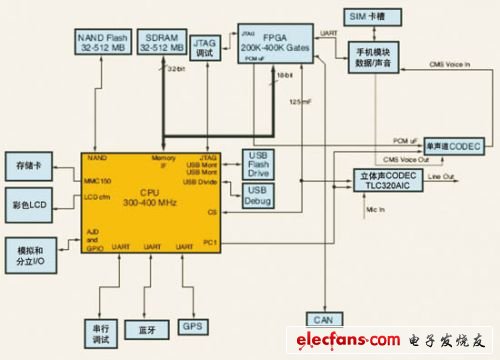
Figure 1 Microsoft telematics hardware platform architecture 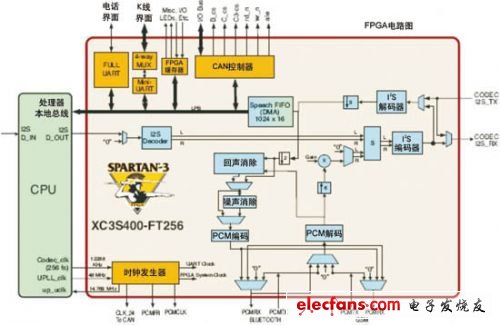
Figure 2 Xilinx spartan3 FPGA design 
Figure 3 Multi-screen display technology example 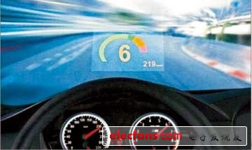
Figure 4 HUD system of the BMW X5 series X6 series
Car navigation information system 
Figure 5 Relationship between MOST, iNIC and vehicle information platform
This network must contain connection points so that end users can connect to devices that are not included in the car and are purchased separately. The most likely scenario is that there is more than one private network. A "trusted" network will support the equipment that has been installed before the car leaves the factory. Users can connect to the user device through a second "untrusted" network. We can implement access control between the two domains through a gateway. 
Figure 6 Schematic diagram of the structure of the vehicle remote fault diagnosis system 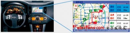
Figure 7 STAR WINGS project schematic 1 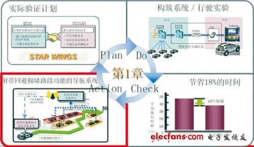
Figure 8 STAR WINGS project schematic 2 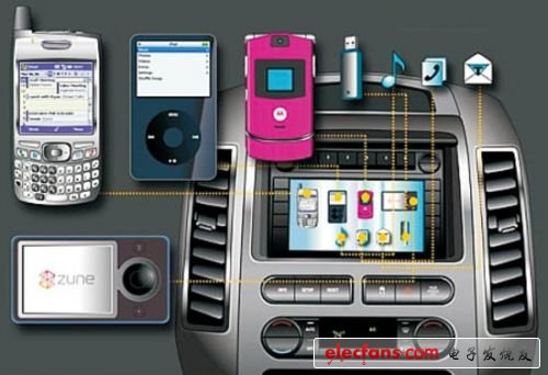
Figure 9 Schematic diagram of the car computer operating system Sync