introduction This article refers to the address: http:// With the development of automotive electronics technology and the continuous improvement of automotive performance requirements, there are more and more electronic devices on the car. In a high-end car designed with traditional wiring methods, the length of the wires can reach 2km, the number of electrical nodes can be as high as 1500, and the speed of development is about doubled every 10 years. Under such circumstances, the contradiction between the thick wire harness and the limited available space in the car is becoming more and more acute, and it is also the biggest obstacle for the car to be lightweight and further electronic. The development of computer networking has made it possible to solve this problem. Since the late 1970s, major automobile manufacturers have begun research on vehicle networks, and standardization research on vehicle network protocols has also rapidly developed abroad. By the early 1990s, the development of the agreement reached a relatively mature stage. Due to the wide variety of automotive electrical systems, the transmission speed and cost requirements of the network varied greatly, so it showed a diversified trend. More prominent among these vehicle agreements is the CAN (Controller Area Network) proposed by BOSCH in the early 1980s. There are also network protocols for different transmission rate grades and special applications, such as low-speed LIN, medium-to-high-speed SAE J1939, KWP2000 for diagnostics, TTP for X-by-wire, and MOST for multimedia applications. Electric vehicles were born to solve the fuel crisis and environmental pollution problems. Compared with traditional cars, its electronic devices are more and more related to each other, so data communication is more important. The control system in various types of electric vehicles collects parameters reflecting the running status of the vehicle and parts and the driver's will in real time, and sends relevant running instructions. The implementation of these functions places high demands on the communication between the ECUs and directly affects the running performance and safety of the vehicle. The research on China's traditional vehicle network, bus and communication protocol started late and the foundation is quite weak. At present, under the support of the National “10th Five-Year Plan†863 Program, CAN bus is widely used in all electric vehicle vehicles. In the process of independently researching and developing electric vehicles, we should learn from and absorb foreign experience and formulate networks, buses and communication protocols for electric vehicles, which can improve China's technical level in this respect more quickly. The development of the vehicle system network requires the construction of a simulation system to simulate the network, adjust and improve the design. The formulation and implementation of the network protocol must be evaluated by simulation or actual testing of its core performance indicators, so as to ensure the normal operation of the network and meet the requirements of the system in practical applications. This process is required for each ECU node on the network. The CAN bus test bench for vehicles is developed under the special support of the national “10th Five-Year Plan†863 plan electric vehicle. Through the construction of the public platform, the vehicle bus protocol can be simulated and tested to evaluate the performance of the vehicle system network. And can test and evaluate the communication performance of key components. Review on Existing CAN Bus Network Analysis and Evaluation Methods The mathematical modeling method is to establish a mathematical model of the system, which is solved by deductive reasoning. The model expresses the characteristics and behavior of the system in mathematical form, and uses computer-assisted operations to analyze the performance of the network. According to the different structures of the network, make some reasonable approximations and assumptions, and establish some rough relational expressions to represent the relationship between the parameters. Network conformance testing is the test of whether an application is compatible with a given specification or protocol. After the network protocol is developed, each development unit will independently develop components according to the agreement. When different components form a network, components of different development units may not communicate normally. Conformance testing is to test whether the components produced by different manufacturers can communicate normally, and complete a limited number of independent experiments through empirical selection. The conformance test tool sequentially and structurally tests the content described in the conformance test protocol, and the test content can be classified according to the real-time requirement level. In automotive applications, some tests have become international standards, such as ISO 16845, which describes CAN compliance testing. Direct test analysis is a system performance evaluation using test equipment on a real CAN bus. The main indicators for evaluating the core performance of the bus system are: bus transmission rate; bus throughput; bus utilization; message transmission delay time; node ECU communication load; bus EMC characteristics. CAN analysis tools range from the lowest-end RS232CAN analyzer to Vector's range of CAN test and simulation equipment for testing CAN networks. Their main feature is the analysis of data running on the bus. The above three evaluation methods have different characteristics, each of which has certain limitations. There is a big gap between the model simulation and the specific implementation. This gap may make the simulation results unable to be physically realized. The limitations of using a computer software simulation node with strict time rules to replace the partial simulation of the real nodes of the out-of-order messages present on the bus are obvious. At present, the existing network test products are limited to analyzing the data running on the bus, and the correlation with the specific system is not large. Development and application of CAN bus real-time simulation test platform Development of CAN bus real-time simulation test platform The topology of the CAN bus test platform is shown in Figure 1. It consists of a real-time simulation node, a node to be tested, and related software running on a PC. The real-time simulation node consists of a real node composed of a microprocessor and a Philips SJA100 CAN controller. It receives configuration information sent by the configuration and monitoring software running on the PC through RS485, simulates the communication function of a specific ECU, and periodically sends a specific communication to the bus. Information, receive information from the bus, and upload its operating status; the node to be tested is the ECU node in the real network system; run some related test software on the PC, such as: CANoe, CANScope and simulation node configuration software and monitoring software. The test platform can test various indicators of the system, such as bus load, transmission delay, error statistics, communication load analysis of MCU and the influence of various interferences on the bus. The quality of the waveform determines the reliability of the data transmission. Therefore, the physical layer of the CAN bus is evaluated to evaluate the distribution effects of the transmission medium, the bus CAN transceiver, and the termination resistor. The CANscope network oscilloscope is the CAN physical layer analysis tool. It is connected to the PC via a serial bus. The recording module digitizes the messages on the CAN bus and stores them for analysis using software. The pre-trigger mode captures the data of a frame of CAN messages or adjacent frames of an error frame. The analysis software displays the bus voltage value, the differential voltage value, and the change in the fill bit over time. The CAN message frame, the various components of the message frame, and the error frame can be displayed in the trace window. The CAN network has a strong error handling capability. When a node in the network suffers severe interference, it can automatically leave the bus without affecting the information interaction of the entire network. ISO 11519-2 specifies the fault tolerance of the CAN bus for node failure, so the fault tolerance of the CAN network for interference or node failure is measured as required. In order to test whether the network can work normally even if it is interfered or the node fails, CANstress analog bus interference tool can be directly connected to the CAN bus. Through software control, various interferences and malfunctions can be simulated to observe the network. Operation in the event of interference and malfunction. It works in two ways. One is to destroy the message sent by the node to test the network's anti-interference ability. Another way is to set up an external device to simulate a failed node. Application of CAN bus real-time simulation test platform Below are a few test examples of individual ECU communication functions, system topology, and communication media selection. Through testing, the performance of the entire network system can be further improved. (1) Comparison test of real-time performance of a single ECU communication part The purpose of this test is to observe the influence of related software functions on message delay. Figure 2 shows the comparison diagram before and after software modification of the message transmission cycle. Through testing, it is found that the delay of a certain message is relatively large, and further optimization by software can eliminate the delay phenomenon. With the use of CAN bus in automobiles, distributed real-time systems are increasingly used in automobiles. In distributed real-time systems, the real-time nature of the network directly affects the real-time nature of the system, and the real-time nature of the network is mainly determined by the nature of the network, the information traffic, and the response speed of each node in the system to the network information. When the network nature and information traffic of the system are basically determined, what is directly related to the real-time nature of the network is the response speed of each node to the network information. However, the commonly used CAN bus test systems do not have this test function. When they are used for distributed real-time system network test, it is difficult to involve the real-time nature of the network. When developing the bus test platform, considering the characteristics of the whole system, the network-in-the-loop design method is proposed, and the real-time nature of the network is taken as an important factor in the real-time performance of the whole test system throughout the design, analysis and testing process. The CAN bus real-time simulation test platform lays a good foundation for researching and developing China's own electric vehicle communication protocol and testing and evaluating the performance of the CAN bus communication network. At the same time, it can be used for the development of automotive CAN bus related technologies. For different performance CPUs, the performance of the entire test system will be quite different. For this reason, a test system with a higher performance CPU as the core is being developed to meet the needs of the growing vehicle control system. Coaxial Cable ,Pigtail Coaxial Cable,Aerial Fiber Optic Cable Shenzhen Hongyan Wire Industry Co., Ltd. , https://www.hy-cable.com
At present, the analysis and evaluation methods for CAN bus mainly include mathematical modeling, network consistency analysis and direct test analysis. Among them, mathematical modeling is usually used in the initial development of the network system and in the development process, it is planning the entire network. The consistency test and the direct test analysis are mainly carried out in the later stage of development, and the network is put into use, which is used to evaluate the network performance.
The existing testing tools can not easily evaluate the CAN communication of a distributed real-time control network. To this end, we proposed the network-in-the-loop design idea and developed a CAN bus real-time simulation test system. Based on its own R&D platform, the whole system can analyze, test and evaluate the performance of CAN bus communication network and single ECU communication function by using the products of advanced bus test tools. 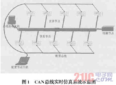
CANoe is a tool for monitoring and analyzing CAN communication networks, with powerful system simulation capabilities. CANoe can establish the simulation structure of the system and the database of nodes, messages and signals. By using its programming language CAPL, node simulation can be performed, and the data on the bus can be dynamically tracked and statistical information can be displayed. The bus data it can measure is: bus load, peak load, bus frame data and frame count statistics, message transmission and reception delay on the PC.
Application platform can evaluate the communication capability of the system, and can test various indicators of the system, such as bus load, peak load, bus frame data and frame count, transmission delay, error statistics, MCU communication load analysis and The impact of various disturbances on the bus, etc. At the same time, the physical layer and network topology of the CAN bus can be evaluated and optimized to evaluate the distribution effects of the transmission medium, the bus CAN transceiver, and the terminating resistor. 
(2) Comparison test of different network topologies The system can be used to test the anti-jamming capability of the bus when comparing different topologies. Figure 3 shows the comparison of the transmission waveforms of the terminal resistance position change signals. It can be seen from the figure that the difference in the position of the terminating resistor has a great influence on the anti-jamming capability of the bus system. In the actual system, attention should be paid to its distribution position. 
(3) The signal transmission waveform of the communication medium is not properly selected. The selection of the communication medium is crucial for the communication of the bus system. Figure 4 shows the physical layer signal diagram of a communication medium. Compared with the physical layer signal diagram after the termination resistor adjustment in Figure 3, the anti-interference ability is significantly reduced. Therefore, when designing the system, you should choose the communication medium. 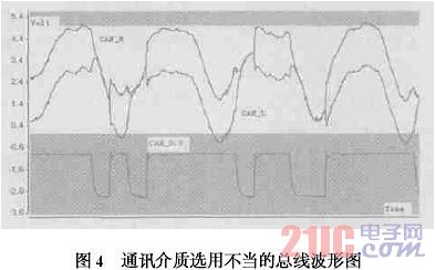
Conclusion