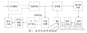
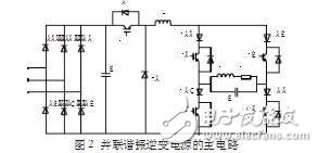
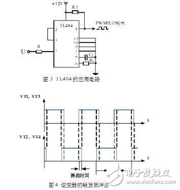
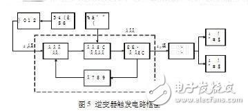
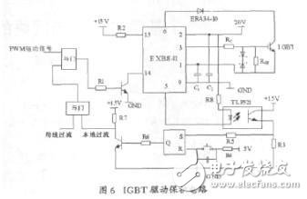
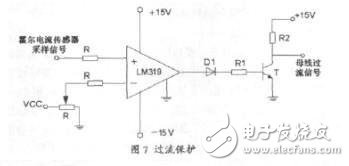
Foreword In the industrial industries of metal melting, bending, hot forging, welding and surface heat treatment, induction heating technology is widely used. Induction heating is based on the principle of electromagnetic induction. It uses the heat generated by the eddy current in the workpiece to heat the workpiece. It has high heating efficiency, high speed, good controllability, easy to achieve high temperature and local heating, and easy to realize mechanization and automation. With the development of power electronics and power semiconductor devices, the basic topology of induction heating power supplies has been continuously improved, generally consisting of rectifiers, filters, inverters and some control and protection circuits. The inverter plays an important role in the induction heating power supply. According to the characteristics of the inverter, the inverter power supply is divided into two types: series resonance and parallel resonance. In this paper, a parallel resonant inverter power supply design scheme for induction heating is proposed, which is analyzed and designed for its main circuit, chopper circuit and inverter control circuit. Circuit composition and design The system block diagram of the power supply is shown in Figure 1. The three-phase AC voltage is converted to a DC voltage after being controlled by the rectification and filtering circuit. The voltage is sent to the DC chopper for chopper regulation and becomes a power-adjustable approximate constant current. After the source is input to the inverter, then the induction heating load is controlled. The DC chopping control part detects the current signal of the chopping output through the sensor, and controls the output pulse width of the PWM through the PI regulator, thereby changing the magnitude of the chopping output current and realizing the closed-loop control. The inverter control part uses the phase-locked loop frequency tracking circuit to control the operating frequency of the inverter, generates a high-frequency trigger pulse, and drives the on and off of the power device in the inverter circuit. The main circuit of the main circuit 1 and the parallel resonant inverter power supply is composed of a three-phase uncontrolled rectifier bridge, a DC chopper, a current source parallel resonant inverter and a load matching circuit (Fig. 2). Here, the unregulated rectification plus chopping wave is used to form a DC current source, mainly considering the advantages of fast protection speed and small filter size caused by high frequency chopping. The main power devices (VT and VT1, VT2, VT3, VT4) in the chopper and inverter use IGBT tubes. A diode is connected in series with each IGBT of the inverter bridge arm, and the forward current through the IGBT will also pass through the series diode. This requires the series diode to pass a large forward voltage and withstand a high reverse voltage. Therefore, VD1~VD4 is a quick recovery diode. The inverter switches regularly through the semiconductor switch, and obtains a certain frequency of alternating current on the load side. The frequency is determined by the operating frequency of the switch. Since the current source is supplied, the output current of the inverter is approximately square wave, and the load is applied to the fundamental wave. The component is high-resistance, the voltage drop is large, and the voltage drop generated by the harmonics of three or more times is small, and the output voltage (that is, the voltage across the capacitor C) can be approximated as a sine wave. PWM chopping control The implementation of chopping is to control the magnitude of the current by controlling the conduction of the IGBT (VT tube in Figure 2) to indirectly control the power. In the steady state operation, in order to understand the change of the load in real time, it is necessary to feedback the change of the current from the resonant circuit, and obtain the duty ratio by comparing with the reference value. The current detection in the system block diagram of Figure 1 can use the Hall current sensor to detect the input current of the inverter DC bus. The control circuit adopts a PI regulator, which is composed of an op amp, a resistor, a capacitor, etc., and can compare the detected current with the set current. As long as the feedback and the setting are deviated, the feedback can be adjusted to approach the set value until it is equal to Set the value to achieve no-difference adjustment and improve system stability. PWM pulse width control uses TL494, which is a widely used PWM control chip with strong anti-interference ability, simple structure, high reliability and low price. In this design, the specific circuit is shown as in Fig. 3: input (ie PI regulation output) is introduced from pin 1, pin 13 is connected to low level, PWM pulse signal is output from pin 8, and the chopper component is triggered by the drive module amplification. IG- BT conduction. Inverter trigger control In the trigger control of the parallel resonant inverter, in order to avoid a large induced potential on the large inductance Ld, the current must be continuous, so to ensure that the inverter is in the commutation, the two sets of bridges VT1, VT3 and VT2, VT4 The principle of first turn-off and turn-off should be followed, that is, the trigger pulses of the two sets of bridge arms are required to have overlapping regions, which is quite different from the series resonant inverter. Figure 4 is the waveform of the inverter trigger pulse. Heating the workpiece will cause a change in the resonant frequency during the heating process. In order for the inverter to work reliably, the inverter needs to always operate in a quasi-resonant or resonant state with a power factor close to or equal to 1 to achieve zero voltage switching of the inverter device. flow. Figure 5 shows the construction of the inverter trigger control circuit. The load sinusoidal voltage of the inverter is taken as the input reference voltage of the phase-locked loop PLL. Samples, zero-crossing comparison, get U1 (t), taking into account the trigger, the delay of the drive circuit and the switching device, etc., the phase compensation circuit is added inside the PLL to form a phase-free phase-locked loop circuit. The output current of the phase-locked loop is realized by U2(t), the two-way voltage U2(t) and the input U1(t) can realize zero phase difference, and the output of the inverter can realize the inverters VT1~VT4 in FIG. Trigger pulse waveform. IGBT drive and protection circuit This power supply uses IGBT as the inverter switch and DC chopper device. Although it has the advantages of large current capacity, small driving power and high switching frequency, the IGBT overcurrent and overvoltage capability is weaker than that of the thyristor, especially its ability to withstand back pressure is more fragile. . Therefore, the performance of the IGBT drive and protection circuit directly affects the reliability and efficiency of the power supply operation. In this design, the IGBT is driven by the EXB841 integrated drive circuit of Japan Fuji Electric Co., Ltd. It is suitable for driving IGBTs below 300A/1200V, and its maximum operating frequency is 40kHz. Figure 6 shows the IGBT drive protection circuit. When the IGBT is overcurrent or short-circuited during fault or debugging, it can be protected by the current protection function inside the EXB841 drive circuit. The EXB841 determines the overcurrent based on the detection of the IGBT set- The voltage between the emitters, here in the IGBT collector and the EXB841 6 pin in series with a fast recovery diode EAR34-10, the diode forward voltage drop to 3V, reverse recovery time 150ns. Can effectively improve the EXB841 overcurrent Judging sensitivity and enhancing protection. In order to prevent the IGBT from being disturbed by external interference, the gate voltage is too high, causing the device to be mis-conducted, especially in a converter or inverter with upper and lower arms, which is easy to cause short-circuit of the same arm. A resistor RGE is connected in the gate emitter, and two reverse-connected Zener tubes are connected in parallel between the gate emitters. In the design, RS flip-flops are also added: When the IGBT is over-current, the 5-pin level of the EXB841 is low, the S-side of the RS flip-flop goes high, and the output Q outputs a high level, which is output through the triode. The local overcurrent signal is low, and this level is added to the AND gate to block the input signal of the EXB841, so as to timely withdraw the gate signal and protect the IGBT. Another signal that can block the input of the EXB841 is the bus overcurrent signal. As shown in Figure 7. When the inverter output is short-circuited, the inverter drive circuit is not working properly, or the commutation fails, it will cause short-circuit overcurrent. The current of the DC bus input by the inverter is monitored by the Hall current sensor, converted into a voltage signal, and sent to the high-speed comparator to compare with the reference voltage. When the reference voltage is exceeded, it indicates that an overcurrent condition occurs in the bus, and overcurrent protection occurs. action. The comparator outputs a high level and the transistor is turned on, then the output is low for reliable overcurrent protection. Conclusion The PI chopper power control circuit of this design uses PI regulation closed-loop control to improve the stability of the system. The design of the phase-locked loop inverter frequency tracking circuit can realize the automatic tracking of the resonant working frequency when the load parameters change during the heating process, so that the inverter works in the capacitive near-resonance state to ensure the safe operation of the inverter. Winnowing Machine,Winnowing Rice,Seed Winnowing Machine,Grain Winnowing Machine Hunan Furui Mechanical and Electrical Equipment Manufacturing Co., Ltd. , https://www.thresher.nl