A ventilator is an instrument that can replace a person's breathing function or assist a person's breathing function. It is suitable for patients with respiratory failure and even breathing to do artificial respiration. It can help patients correct hypoxia and excrete carbon dioxide, and is an important tool to save the lives of some critically ill patients. This article refers to the address: http:// Corn Sheller,Hand Corn Sheller,Corn Sheller Machine,Hand Crank Corn Sheller Hunan Furui Mechanical and Electrical Equipment Manufacturing Co., Ltd. , http://www.thresher.nl
Most of the existing ventilator products are based on single-chip microcomputers. For products with stronger functions, high-end single-chip microcomputers are needed. This makes the system cost relatively high, and there are many peripheral interface modules and complex structures. Using SOPC (Programmable System-on-Chip) technology to design the master control system, you can take full advantage of the powerful functions of the IP core and streamline the number of peripherals. At the same time, it only takes up a small amount of resources, greatly improving the cost performance of the system.
This paper uses SOPC technology to design the main control system of continuous positive airway pressure ventilator. It uses Altera's Nios II soft core processor and some common IP cores. I customized the components based on Avalon bus specification and will control the logic. Integrated into a single FPGA.
Medical ventilator
The positive pressure ventilator uses the method of increasing the pressure in the airway to deliver air into the lungs, and the pressure in the lungs increases to expand the lung cavity. When the pressure is lost, due to the elasticity of the lung cavity tissue, the lungs are restored to their original shape, and a part of the exchanged air is exhaled. At present, most ventilators use this method of increasing the pressure in the airway to aerate the patient.
The air pressure required by the ventilator is provided by a DC motor. The control signal of the DC motor is a PWM signal, and the rotational speed of the motor is controlled according to the duty cycle and the period of the PWM signal. The external interface provides buttons to accept commands and set various parameters. The prompt information, status information, and parameter information are displayed on the character LCD. In order to facilitate testing of the system, the UART is used as a command control interface to directly control the system, and the interface is hidden after the finished product.
system structure
The block diagram of the main control system of the ventilator with SOPC technology as the core is shown in Figure 1. 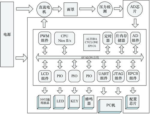
Figure 1 ventilator system hardware block diagram
The core FPGA of the main control system uses the EP1C6T144C8 of Altera's Cyclone series. The CPU is the Nios II soft core processor, which manages the entire system. In the folding line frame as the main control board, in addition to the PC for downloading and debugging, the DC motor and the main control board must be separately powered. After the DC motor is working, the airflow is sent to the mask, and the motor adjusts the airflow according to the signal of the end. A pressure detecting module is installed in the mask, and is returned to the main control board through A/D conversion for feedback adjustment of the airflow. The mask is for the patient to use.
DC motor control
The system uses a PWM signal to control the DC motor. There is no PWM component in the standard IP core provided by SOPC Builder. It needs to be customized. The output signal of the PWM component is square wave, and the period and duty cycle of the square wave are adjustable. The logical structure of the PWM task is shown in Figure 2. 
Figure 2 PWM task logic structure
The task logic of the PWM component is:
The PWM task logic consists of an input clock, an output signal, an enable bit, a 32-bit counter, and a 32-bit comparator;
â— The clock drives a 32-bit counter to establish the period of the output signal;
The comparator is used to compare the current value of the 32-bit comparator with the duty value to determine the output signal;
â— If the current value is less than or equal to the duty cycle value, the output logic signal is 0, otherwise it is 1.
Register file for the PWM component:
â— clock_divde the number of clock cycles in one cycle of the PWM;
â— duty_cycle The number of clock cycles when the PWM output is low;
â— Enable/disable of the enable PWM output. A rising edge of 0 to 1 enables the PWM component.
The header file and driver of the PWM definition register are encapsulated with:
Altera_avalon_pwm_init(); //PWM module initialization, including cycle settings
Altera_avalon_pwm_enable(); //PWM module enable
Altera_avalon_p wm_disable(); //PWM module is forbidden
Altera_avalon_ pwm_change_duty _cycle(); //PWM module duty cycle adjustment
For DC motors, the PWM duty cycle needs to reach a certain amount to make the motor work. The PWM signal below the threshold (PWM_DUTY_THRESHOLD) cannot drive the motor. This part of the energy is converted into heat damage to the motor. Therefore, when setting the PWM value. It is necessary to note that the value is set above the threshold, and the set value is judged in altera_avalon_pwm_change_duty_cycle(). If the value is lower than PWM_DUTY_THRESHOLD, it is adjusted to PWM_DUTY_THRESHOLD+1.
After all the above designs are completed, they are packaged into SOPC components in SOPC Builder.
Output and indication module
The system needs to input settings, controls, and display prompts. These functions include button input, LED indicator output, buzzer output, and LCD output.