Waiting for your phone to charge is a thing of the past, Quick Charger pumps up to 18 W/30W/45W into your compatible smart phone or tablet, reducing charge time by up to 75% compared to conventional charger.
High quality ,competitive price and good servie, MLF welcome you. Please don't hesitate contact us if there is any question on the perfomance of switching power adapter .
Phone Charger Station,Iphone Charger Station,Charger Station Meile Group Limited , https://www.hkmeile.com
Overview In general, the transmit antennas operating in the 260MHz to 470MHz industrial, scientific, and medical frequency band (ISM) are very small and can only radiate a small portion of the output power of the transmitter power amplifier. From this point of view, the measurement of the transmission power is very important. The specific measurement work is very complicated, because the 15.231 part of the FCC specification specifies the field strength (V / m) limit at 3 meters from the transmitter. In addition, the placement of the receiving antenna and the receiving unit used in the measurement will affect the measurement of the radiated power.
This article will explain the relationship between radiated power and field strength and the measurement receiver. The table gives the corresponding relationship between the FCC field strength requirements of the 260MHz to 470MHz frequency band and the radiated power, and gives the typical parameters measured by the receiver. Through the above relationship, some conversion factors can be understood, and the user can determine whether the measurement result of the receiver indicates that the transmitter is close to its radiated power limit.
The relationship between the field strength and the radiated power. The antenna transmit power extends to the surroundings (spherical). If the antenna has directivity, the power change along the propagation direction conforms to the expression of its gain G (Θ, Φ), (Θ, Φ). For any point on the sphere of R, the power density (PD) in watts per square meter is given by Equation 1: 
This equation is simply expressed as the transmitted power divided by the spherical area of ​​radius R. The gain sign, GT, has no angle change. Because most of the antennas used in the 260MHz to 470MHz ISM band are very small compared to the operating wavelength, the template will not change drastically with the direction. Because the antenna is a very low-efficiency radiator, the gain is very small. For this reason, PT and GT are multiplied to represent the equivalent isotropic radiated power (EIRP) of the combined transmitter and antenna. EIRP represents the power that can be transmitted from an ideal omnidirectional antenna.
The power density at the distance from the transmitter R can also be expressed as the square of the radiated signal field strength E divided by the impedance of the free space expressed by η0 (Equation 2). The magnitude of η0 is 120πΩ, or 377Ω. 
From the above two equations, the relationship between EIRP, PTGT and field strength E can be derived in V / m. 
Rearrange formula 3 and express EIRP in the form of field strength: 
At a distance of 3 meters required by the FCC, this relationship is: 
Assuming that the FCC limits the average field strength of 315MHz to 6mV / m, using Equation 5, the average radiated power limit is 10.8µW, or -19.7dBm.
The conversion from field strength to EIRP is more complicated because some documents express the field strength in logarithmic or dB form. In the above example, the field strength of 6mV / m can be expressed as 15.6dBmV / m or 75.6dBµV / m.
In addition, the FCC radiation limit varies with frequency in the frequency range of 260MHz to 470MHz. This change means that for each frequency, the field strength needs to be calculated according to the FCC requirements, and then converted from one measurement unit to another. . The 15.231 part of the FCC specification stipulates that the field strength at 260MHz is limited to 3750µV / m, and linearly increases to 12500µV / m at 470MHz.
The results shown in Table 1 are obtained according to the restrictions on the average field strength according to Equations 1 to 5 and the FCC specifications. The data in Table 1 provides multiple expressions of the field strength specifications at intervals of 5 MHz. The gain of the transmitting antenna is assumed to be 0dB.
Table 1. EIRP and FCC norm 15.231 average field strength limits Frequency MHz Field Strength µV / meter Field Strength dBµV / meter EIRP mW EIRP dBm 260 3750 71.5 0.004 -23.7 265 3958 72.0 0.005 -23.3 270 4167 72.4 0.005 -22.8 275 4375 72.8 0.006 -22.4 280 4583 73.2 0.006 -22.0 285 4792 73.6 0.007 -21.6 290 5000 74.0 0.007 -21.1 295 5208 74.3 0.008 -20.9 300 5417 74.7 0.009 -20.6 305 5625 75.0 0.009 -20.2 310 5833 75.3 0.010 -19.9 315 6042 75.6 0.011 -19.6 320 6250 75.9 0.012 -19.3 325 6458 76.2 0.013 -19.0 330 667 76.5 0.013 -18.8 335 6875 76.7 0.014 -18.5 340 7083 77.0 0.015 -18.2 345 7292 77.3 0.016 -18.0 350 7500 77.5 0.017 -17.7 355 7708 77.7 0.018 -17.5 360 7917 78.0 0.019 -17.3 365 8125 78.2 0.020 -17.0 370 8333 78.4 0.021 -16.8 375 8542 78.6 0.022 -16.6 380 8750 78.8 0.023 -16.4 385 8958 79.0 0.024 -16.2 390 9167 79.2 0.025 -16.0 395 9375 79.4 0.026 -15.8 400 9583 79.6 0.028 -15.6 405 9792 79.8 0.029 -15.4 410 10000 80.0 0.030 -15.2 415 10208 80.2 0.031 -15.0 420 10417 80.4 0.033 -14.9 425 10625 80.5 0.034 -14.7 430 10833 80.7 0.035 -14.5 435 11042 80.9 0.037 -14.4 440 11250 81.0 0.038 -14.2 445 11458 81.2 0.039 -14.0 450 11667 81.3 0.041 -13.9 455 11875 81.5 0.042 -13.7 460 12083 81.6 0.044 -13.6 465 12292 81.8 0.045 -13.4 470 12500 81.9 0.047 -13.3
The relationship between received power and radiated power If the unit of measurement of received power and radiated power is restricted, the power relationship between reception and transmission will be easily understood, which is the basis for calculating space loss in a communication system.
Starting from the power density at a certain distance R (Equation 1), the received power of the antenna at this distance is the power density times the effective area of ​​the receiving antenna. The effective area of ​​the antenna is defined by Equation 6: 
λ is the emission wavelength, and the effective area of ​​the receiving antenna is multiplied by the density expressed by Equation 1, and the free space loss calculation formula can be obtained: 
Equation 7 shows that if the gain of the receiving antenna remains uniform (a small-size antenna is used, a quarter wavelength), for a receiving antenna with a uniform gain, the frequency is 300MHz (corresponding to a wavelength of 1 meter), and the power loss at 3 meters is probably (1 / 12Ï€) 2, or 31.5dB. This value will vary depending on the gain of the receiving antenna, ranging from 25dB to 35dB. This step is important to first confirm that the transmitter, antenna, and test device are reasonable. For example, if you want the RKE transmitter circuit board to radiate -20dBm of power, you should see a power of slightly less than -50dBm on a spectrum analyzer connected to the receiving antenna at 3 meters, assuming that the receiving antenna maintains a uniform gain.
Testing the relationship between received voltage and radiated power In many tests designed to prove compliance with FCC regulations, the receiver usually measures the RF voltage at the antenna, not the power. This is because FCC requires field strength measurement, not EIRP. The unit of field strength is V / m (or mV / m or µV / m). It is more intuitive to obtain V / m by measuring the voltage and converting it through the calibration constant.
In order to measure the electromagnetic compatibility of the receiving antenna during production, a calibration constant in units of 1 / m is given. We will discuss the significance and origin of this calibration constant below, and explain the importance of the relationship between voltage measurement and EIRP. When the receiver obtains the power from the antenna, this power is usually converted into a voltage by the load resistance Z0 of 50Ω. The relationship between the received voltage and the received power is expressed by Equation 8: 
Bring the above equation into Equation 7 to get the received voltage expression expressed by EIRP (Equation 9): 
Test the relationship between the received voltage and the field strength to establish the relationship between the received power or the received voltage and the field strength can be done by Equation 6 and Equation 7. Multiplying the power density and the effective area of ​​the receiving antenna, the only difference in Equation 10 is that the power density is represented by the field strength E, similar to Equation 2: 
According to the relationship between PR and received voltage expressed in Equation 8, the relationship between VR and E is derived as: 
The square root operation is performed on both sides of the equation, and the resulting received voltage is a coefficient multiplied by the field strength. Most receivers have an impedance Z0 of 50Ω, η0 = 120πΩ, and the above equation can be simplified to Equation 12: 
The relationship coefficient between the field strength E and the received voltage VR is usually expressed by the ratio of E and VR. This is because VR is a measured value and E is a value compared with the FCC standard. The antenna manufacturer lists the coefficient when measuring the field strength, and calls it the antenna factor (AF). This coefficient is related to the frequency in the specification.
The antenna coefficient obtained from Equation 12 is as follows: 
The unit of Equation 13 is expressed in 1 / m or 20 log10 [V / m / V], dB. The antenna gain is expressed by the power gain, so the 6dB antenna gain coefficient is 4, and the 10dB antenna gain coefficient is 10. If the wavelength is 1 meter (300MHz frequency) and the antenna gain is 6dB, the antenna coefficient in Equation 13 is 4.87 / m, or 13.6dB / m.
A common receiving antenna used for field strength measurement is a log-period array (LPA) antenna, and its gain has nothing to do with frequency in the test range. This means that the antenna factor increases linearly with frequency. A typical LPA, TDK RF SoluTIon's PLP-3003, has an antenna coefficient of 14.2dB at 300MHz, or 5.1 / m. The relationship between antenna coefficient and frequency is shown in Figure 1. According to Equation 13, at a frequency of 300 MHz, the gain of this antenna is 5.6 dB. 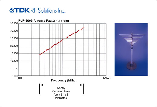
Figure 1. Typical measurement antenna coefficient (AF) versus frequency
According to Equation 13 and Figure 1, in order to meet the FCC's average field strength limit of 5417µV / m at 300MHz, the results measured at the 50Ω input receiver should be within 1056µV. When expressed in dB, the FCC field strength limit of 74.7dBµV / m corresponds to the measured value of the receiver of 60.5dBµV and the measured power of -50. This result is consistent with the previous power loss estimate (thus, we get an EIRP signal of -20dBm at the transmitter, which will be received by the receiver at approximately -50dBm.).
Measure the received voltage and power Table 2 gives the measured voltage at the 50 Ω load receiving antenna that meets the FCC field strength limit. The AF used in Table 2 is taken from the specification of the logarithmic periodic array antenna in the figure. Table 3 shows the power values ​​measured under the same device. The effective radiated power shown in Table 3 comes from the transmitter and antenna that meet the field strength limit. The space loss and receiving antenna gain determine the power on the 50Ω load. The results in the two tables are consistent. These tables provide a reference for designers and users of shortwave UHF transmitters to help determine whether the system meets FCC requirements and can provide the required power.
Actual measurement considerations The table in this article gives the measured values ​​of power and voltage, which are functions of the field strength and EIRP in the specification. These values ​​will vary depending on the test antenna used. In the measurement, it is also necessary to refer to the correction factor and consider the cable loss, mismatch loss, etc. These factors are related to the frequency. The test environment, especially the reflection from the ground, can cause a significant change in the received voltage (up to 6dB). To calibrate the ground reflection, another reference antenna can be used, usually a dipole antenna. The polarization of the radiating antenna needs to match the polarization of the measuring antenna as much as possible. The directional template of the radiating device needs to be considered, even if the size of the radiating antenna is very small (less than 1/6 wavelength), because the encapsulation, test equipment, and the ground shield of the coaxial cable will cause a change in directivity.
The field strength in these tables refers to the average power limit allowed by the FCC regulations. If the transmission duration and duty cycle meet certain restrictions, the peak radiation power is limited to about 20dB. Therefore, designers need to pay special attention to situations that are significantly higher than the data listed in the table. Because the test value meets the field strength limit, it is not difficult to adjust the device. For example, if the duty cycle of a product allows the peak field strength at 315MHz to be 10dB higher than the FCC average field strength, then the peak field strength can be 19.1µV / m, or 85.6dBµV / m. The corresponding voltage and power of Table 2 and Table 3 are 71dBµV and -36dBm.
After measuring and obtaining all these parameters, you can use the table provided here to determine whether the transmitter meets the design requirements.
Table 2. Tested receiver voltage in FCC field strength limits Frequency MHz Field Strength µV / meter Field Strength dBµV / meter Meas. Antenna Gain Meas. Antenna Gain, dB Meas. Antenna Factor,
1 / meter Meas. Antenna Factor, dB (1 / m) Meas. Recv. Voltage, µV Meas. Recv. Voltage, dBµV 260 3750 71.5 3.6 5.6 4.4 13.0 844 58.5 265 3958 72.0 3.6 5.6 4.5 13.1 874 58.8 270 4167 72.4 3.6 5.6 4.6 13.3 903 59.1 275 4375 72.8 3.6 5.6 4.7 13.4 931 59.4 280 4583 73.2 3.6 5.6 4.8 13.6 958 59.6 285 4792 73.6 3.6 5.6 4.9 13.8 984 5939 290 5000 74.0 3.6 5.6 5.0 13.9 1009 60.1 295 5208 74.3 3.6 5.6 5.0 14.1 1033 60.3 300 5417 74.7 3.6 5.6 5.1 14.2 1056 60.5 305 5625 75.0 3.6 5.6 5.2 14.3 1079 60.7 310 5833 75.3 3.6 5.6 5.3 14.5 1101 60.8 315 6042 75.6 3.6 5.6 5.4 14.6 1122 61.0 320 6250 75.9 3.6 5.6 5.5 14.8 1143 61.2 325 6458 76.2 3.6 5.6 5.6 14.9 1163 61.3 330 6667 76.5 3.6 5.6 5.6 15.0 1182 61.5 335 6875 7637 3.6 5.6 5.7 15.2 1201 61.6 340 7083 77.0 3.6 5.6 5.8 15.3 1219 61.7 345 7292 77.3 3.6 5.6 5.9 15.4 1236 61.8 350 7500 77.5 3.6 5.6 6.0 15.5 1254 62.0 355 7708 77.7 3.6 5.6 6.1 15.7 1270 62.1 360 7917 78.0 3.6 5.6 6.2 15.8 1286 62.2 365 8125 78.2 3.6 5.6 6.2 15.9 1302 62.3 370 8333 78.4 3.6 5.6 6.3 16.0 1318 62.4 375 8542 78.6 3.6 5.6 6.4 16.1 1333 62.5 380 8750 78.8 3.6 5.6 6.5 16.3 1347 62.6 385 8958 79.0 3.6 5.6 6.6 16.4 1361 62.7 390 9167 79.2 3.6 5.6 6.7 16.5 1378 62.8 395 9375 79.4 3.6 5.6 6.8 16.6 1388 62.9 400 9583 79.6 3.6 5.6 6.8 16.7 1402 62.9 405 9792 79.8 3.6 5.6 6.9 16.8 1414 63.0 410 10000 80.0 3.6 5.6 7.0 16.9 1427 63.1 415 10208 80.2 3.6 5.6 7.1 17.0 1439 63.2 420 10417 80.4 3.6 5.6 7.2 17.1 1451 63.2 425 10625 80.5 3.6 5.6 7.3 17.2 1463 63.3 430 10833 80.7 3.6 5.6 7.4 17.3 1474 63.4 435 11042 80.9 3.6 5.6 7.4 17.4 1485 63.4 440 11250 81.0 3.6 5.6 7.5 17.5 1496 63.5 445 11458 81.2 3.6 5.6 7.6 17.6 1506 63.6 450 11667 81.3 3.6 5.6 7.7 17.7 1517 63.6 455 11875 81.5 3.6 5.6 7.8 17.8 1527 63.7 460 12083 81.6 3.6 5.6 7.9 17.9 1537 63.7 465 12292 81.8 3.6 5.6 7.9 18.0 1546 63.8 470 12500 81.9 3.6 5.6 8.0 18.1 1556 63.8
Table 3. EIRP indicates the measured value of the received power Frequency MHz Field Strength
µV / meter EIRP mW EIRP dBm Meas. Antenna Gain Meas. Antenna Gain, dB Meas. Recv. Power, µW Meas. Recv. Power, dBm 460 3750 0.004 -23.7 3.6 5.6 0.014 -48.5 365 3958 0.005 -23.3 3.6 5.6 0.015 -48.2 270 4167 0.005 -22.8 3.6 5.6 0.016 -47.9 275 4375 0.006 -22.4 3.6 5.6 0.017 -47.6 280 4583 0.006 -22.0 3.6 5.6 0.018 -47.4 285 4792 0.007 -21.6 3.6 5.6 0.019 -47.1 290 5000 0.007 -21.2 3.6 5.6 0.020 -46.9 295 5208 0.008 -20.9 3.6 5.6 0.021 -46.7 300 5417 0.009 -20.6 3.6 5.6 0.022 -46.5 305 5625 0.009 -20.2 3.6 5.6 0.023 -46.3 310 5833 0.010 -19.9 3.6 5.6 0.025 -46.2 315 6042 0.011 -19.6 3.6 5.6 0.025 -46.0 320 6250 0.012 -19.3 3.6 5.6 0.026 -45.8 325 6458 0.013 -19.0 3.6 5.6 0.027 -45.7 330 6667 0.013 -18.8 3.6 5.6 0.028 -45.5 335 6875 0.014 -18.5 3.6 5.6 0.029 -45.4 340 7083 0.015 -18.2 3.6 5.6 0.030 -45.3 345 7292 0.016 -18.0 3.6 5.6 0.031 -45.1 350 7500 0.017 -17.7 3.6 5.6 0.031 -45.0 355 7708 0.018 -17.5 3.6 5.6 0.032 -44.9 360 7917 0.019 -17.3 3.6 5.6 0.033 -44.8 365 8125 0.020 -17.0 3.6 5.6 0.034 -44.7 370 8333 0.021 -16.8 3.6 5.6 0.035 -44.6 375 8542 0.022 -16.6 3.6 5.6 0.035 -44.5 380 8750 0.023 -16.4 3.6 5.6 0.036 -44.4 385 8958 0.024 -16.2 3.6 5.6 0.037 -44.3 390 9167 0.025 -16.0 3.6 5.6 0.038 -44.2 395 9375 0.026 -15.8 3.6 5.6 0.039 -44.1 400 9583 0.028 -15.6 3.6 5.6 0.039 -44.1 405 9792 0.029 -15.4 3.6 5.6 0.040 -44.0 410 10000 0.030 -15.2 3.6 5.6 0.041 -43.9 415 10208 0.031 -15.0 3.6 5.6 0.041 -43.8 420 10417 0.033 -14.9 3.6 5.6 0.042 -43.8 425 10625 0.034 -14.7 3.6 5.6 0.043 -43.7 430 10833 0.035 -14.5 3.6 5.6 0.043 -43.6 435 11042 0.037 -14.4 3.6 5.6 0.044 -43.6 440 11250 0.038 -14.2 3.6 5.6 0.045 -43.5 445 11458 0.039 -14.0 3.6 5.6 0.045 -43.4 450 11667 0.041 -13.9 3.6 5.6 0.046 -43.4 455 11875 0.042 -13.7 3.6 5.6 0.047 -43.3 460 12083 0.044 -13.6 3.6 5.6 0.047 -43.3 465 12292 0.045 -13.4 3.6 5.6 0.048 -43.2 470 12500 0.047 -13.3 3.6 5.6 0.048 -43.2
Radiation power and field strength test of UHF ISM band transmitter
Abstract: Working in the industrial, scientific and medical (ISM) band, the short-range wireless communication in the frequency range of 260MHz to 470MHz has been widely used in remote keyless entry control systems (RKE), home security and remote control devices. A key parameter of a wireless transmitter is the power transmitted through the antenna. This power must be large enough to ensure the reliability of the transmission to the receiving link. However, this power must also be limited to the radiated power specified in FCC Part 15.231. This article discusses the field strength requirements of the FCC specifications and the typical indicators for receiver testing in the frequency range of 260MHz to 470MHz. The table lists the field test data.