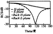
Analysis of Singularity in Integral Equation of 3D Vector Scattering This paper studies the processing method of the singularity of the integrand in the electric field integral equation (EFIE), especially the high-order singularity that appears in the three-dimensional vector scattering analysis, and gives two numerical methods to solve the singularity of the integral equation It is a singular transfer method for calculating O (1 / R) order singular integral [1]. Another method is to solve the numerical calculation problem of O (1 / R2) higher order singular integral, it is by excluding a singular point The finite small block, and the contribution of this small area to the integration is zero, so that the integral equation becomes numerically integrable in the entire integration domain. Singularity Analysis of the Integral EquaTIon for Three Dimension Vector Fields Scattering WANG Hao-gang, NIE Zai-ping Abstract: In this paper, the singularity in the integrand of electrical field integral equaTIon (EFIE) for 3-dimensional vector fields scattering is first analyzed.Two numerical methods for solving the singularity integral equaTIon are developed.One method is the singularity transferring method for calculaTIng integral value containing O (1 / R) singularity in its integrand [1]. The other singularity is removed first and the integral contribution of this small area is proved to be zero.Thus, the integral on the whole integral area can be calculated properly by using numberical method. 1. Introduction With the development of computing technology, numerical methods are more and more widely used in solving the three-dimensional vector scattering problem. The key to solving the three-dimensional vector scattering problem with the moment method is to accurately solve the elements of the impedance matrix, especially the self-impedance elements .Solving these matrix elements requires the area points of the field point and the source point. In the solution of the self-impedance element, you will encounter the problem of generating a singular integral kernel when the field point and the source point coincide. Currently, domestic and foreign scholars have such singular integral Despite some research, it is not satisfactory. Some approximate it [3], which reduces the numerical accuracy of the diagonal elements of the impedance matrix, which directly affects the accuracy of the numerical solution of electromagnetic scattering. The analysis of the singularity of the integrand in the electric field integral equation (EFIE) (the source of the singularity in the integral expression of the self-impedance element) can use the principal value integration method. Since the integrand changes very violently near the singular point, the general numerical integration method cannot be used for the principal value integration. However, since the integral domain in the principal value integration Containing singular points, the integrand is analytic, so it can be easily analyzed numerically. In this paper, two methods of numerically integrating the electric field integral equation in the form of principal value integration are derived. The first is in The singular transfer method [1] is based on the specific scheme of numerical integration of the O (1 / R) order singular integral term in the electric field integral equation. The second is the treatment of O (1 / R2) higher order singular integral term. This method is to remove a finite small area of ​​the integrand near the singular point that changes drastically, and then prove that the integration in this small area is zero, so that the integration becomes numerically integrable, and the electric field integration is satisfactorily solved Solve the equation numerically. Using the method of this paper, the RCS of the conductor ball and the thin-walled cylinder and square plate with open ends are numerically calculated, and satisfactory results are obtained. Second, the singularity of the integral and the principal value of the three-dimensional EFIE integral The electric field integral equation (EFIE) of the three-dimensional conductor vector scattering can be expressed as: Select the appropriate local current basis function {jp (r ′)} to represent the surface current J (r ′) of the metal scatterer, we get: Then select the appropriate weight function {tq (r)} to discretize equation (1) into a matrix equation: Among them, Fq is the excitation term, ap is the response term, and Aqp is the impedance element term. In the parameter space, the integral expression of the impedance element is: In the formula, sq and sp denote the integral domains for the field point and the source point respectively; u1 and u2 and u′1 and u′2 are the coordinates of the midfield point and the source point, respectively. In formulas (5) and (6), when i = 1, j = 2; when i = 2, j = 1, and When sself = sq∩sp ≠φ, Aqp is called a self-impedance element. At this time, the field integration domain and the source integration domain partially or completely coincide. When r ′ → r, R → 0, from equation (4) It can be seen that the integrand diverges. In classical function theory, the integral is meaningless. This poses great difficulties for numerical solution. In the formula, the electric field integral equation is divided into two items. The first item is the main value integral without field points (singular points). The second item is the separated area element integral with field points. Since the main value integral does not contain singular points Therefore, it can be calculated by the usual numerical methods. The following discusses the contribution of the second term to the entire integral equation. It can be proved that [6] regardless of the shape of Δs, when Δs → 0, the self-scattering field Esself and the total field E ( r) has the following relationship: Since the electric field is perpendicular to the surface on the ideal conductor surface, the second term of equation (9) is zero, namely: The above formula is the principal value integral of the electric field integral equation. It is not difficult to see that the difference between equations (1) and (11) is only that: the integral domain of the principal value integral does not contain singularities, so the convergence of its integral value can be analyzed using classical function theory Trend. So, the impedance element calculation formula (4) can be rewritten as: Where r∈sq, Δsself ∈ {Δs}, ∑Δs = sq, Δsself The impedance matrix calculation formulas (4) and (12) can be abbreviated as: with Where r∈sq, Δsself ∈ {Δs}, ∑Δs = sq, Δsself 3. The singular term transfer method In equation (13), it contains only the weak singularity of the Abel integral kernel [7]. Generally speaking, for such integrals, as long as the division of the numerical calculation is as thin as possible (no singularity), The more accurate the numerical result obtained. But the amount of calculation increases. If fewer nodes are taken, the integrand changes drastically near the singular point, resulting in an increase in error. Therefore, it is necessary to find a practical and feasible solution in numerical calculation . One of the methods to deal with this kind of singular integral is the singular transfer method [1]. This paper generalizes this method in order to solve the singular problem like equation (13). After a simple mathematical treatment, we get: In the above formula, the first integrand is continuously finite in the integral domain, so the value is integrable. In the second integral, the factor f1 (r, r) is only related to the field point, so it can be mentioned outside the integral number , So the singular terms are simplified so that the analytical solution of the integral is used: Where R0 = 4. Excavation of finite small block method The numerical integration of I′2 is discussed below. The integral term I′2 does not contain a singular point, and its integrand function F2 (r, r ′) is analytical in the integral domain. Near r, since F2 (r, r ′) changes very sharply with r ′, it is very difficult to find the product with general numerical values. The first term in the formula does not contain abrupt changes, so it can be calculated by the general numerical quadrature method. The second term does not contain singularities, and analytical results can be obtained. Figure 1 Excludes a small block Δs0. (A) The rectangular finite small block corresponding to the parameter space, the midpoint of the rectangle is the singular point (u1, u2); (b) The finite small block corresponding to the real space Δs0; (c) parameter In space, after the singular point (u1, u2) is translated to the origin 0, the polar plot of the finite rectangular block From equation (14), we can see that due to the geometric factors that vary with the source space r ′ In the above formula, A (r) is a factor that does not change with the source point, and When Δs0 << 1, there is R0≈R. among them, Substitute equations (26), (27) into equation (28), and simplify to get I22 = 0. Then equation (20) becomes: I′2 = I21 + 0 = I21. From the above analysis, we can see that the separated small pieces The domain does not contribute to the integration. Therefore, in the actual calculation, it is convenient to use the numerical quadrature method to calculate I′2, and make the integration when the field point equals the source point zero. 5. Numerical results In order to verify the correctness of the above singular integral processing method, three numerical examples are given below. Figure 2-A metal conductor ball with ka = 0.5 and an infinitely thin gold conductor cylinder with open ends are exposed to plane waves from the negative z direction Figure 3 Two-station RCS of the E-plane and H-plane of the conductor ball Figure 4 [2] Numerical results of corresponding conductor spheres Figure 5 E-plane dual-station RCS with thin-walled cylinders open at both ends Fig. 6 [2] Corresponding E-plane dual-station RCS Figure 7 H-plane double-station RCS with thin-walled cylinders open at both ends Figure 8 Reference [2] Corresponding H-plane dual-station RCS Example 3 is the scattering field of a square conductive plate with a length of 5λ on one side (as shown in Figure 10) on the elevation plane φ = 60 ° Figure 9 Two-station RCS of a square plate with a side length of 5λ Fig. 10 [3] Corresponding results of tablet dual-station RCS 6. Conclusion This article first analyzes the singularity of the integral in the electric field integral equation (EFIE), and proposes two methods for numerically solving the singular integral: the first term of Aqp contains O (1 / R) order singularity. The method of singular transfer is introduced, and it is practically generalized to obtain equation (20). Since the transferred term in equation (20) is continuous and finite at the singular point, the product can be obtained by numerical methods, and the singular term can follow the equation ( 19) Analytical results. When dealing with the second term of Aqp (including O (1 / R2) order singularity), the method of digging out small pieces is used, and prove that I22 = 0. To make I22 = 0, the basis function Selected band factor 1 / Carbon Fiber Products Include : Carbon Fiber Boom from ø6mm to ø80mm Thickness from 0.5mm to 10mm ,Carbon Fiber Plate,Carbon Fiber Board thickness from 0.5mm to 10mm, Carbon Fiber Shell Carbon Fiber Boom,Carbon Fiber Plate,Carbon Fiber Board,Carbon Fiber Shell shenzhen GC Electronics Co.,Ltd. , https://www.jmrdrone.com
Keywords: three-dimensional vector scattering; electric field integral equation; self-impedance; principal value integral
(Dept. of Microwave Eng., UEST of China, Chengdu 610054, China)
Key words: 3 dimension vector fields scattering; electrical field integral equation; self-impedance; principal integral ![]() (1)
(1) ![]() (2)
(2) ![]() (3)
(3)  (4)
(4) r /
ui and
r ′ /
ui (i = 1,2) is the tangential vector of points r and r ′ on the surface of the object in real space; g = det (gij), (i, j = 1,2), gij =
r /
ui.
r /
uj, (i, j = 1,2) is the first basic quantity of surface s [4].
In the parameter space, the basis function selects rooftop functions (rooftop functions): ![]() (5)
(5)  (6)
(6) ![]() (7)
(7) ![]() (8)
(8)
However, in practice, the field generated by current is always limited and unique. For this, the principal value integration method of singular integral [5] is used to analyze the electric field integral equation. Equation (1) can be written as:  (9)
(9) ![]() (10)
(10)  (11)
(11) 
sself = sq∩sp, Δsself → 0 (12)
It can be seen from equation (12) that in terms of the area points of the field point and the source point, the integrand contains two items:  (13)
(13) ![]() (14)
(14)  (15)
(15)  (16)
(16) sself = sq∩sp, Δsslef → 0.
Equations (15) and (16) can be used to solve matrix self-impedance elements. However, equation (16) uses principal value integration for the source point to facilitate numerical analysis. In both equations, I1 = I′1, I2 = I′2 . For convenience, choose I1 and I′2. 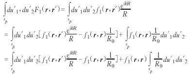 (17)
(17) 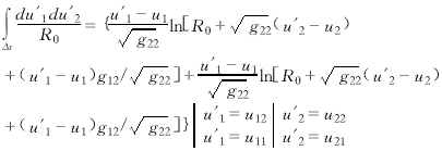
![]() (19)
(19)
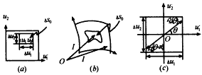
Surround a singular point with a finite small surface block ΔS (ΔS sp), and set the steep part of F2 (r, r ′) in ΔS. Take Δs0 = ΔS-Δsself. In the actual space, Δs0 corresponds to a small surface block, that is, Δs0 << 1. In space, Δs0 is a small rectangular block with a length of Δu1 and a width of Δu2, as shown in Figure 1. At this time, I′2 becomes:
 (20)
(20) 
![]() And the factor 1 contained in jp (r ′)
And the factor 1 contained in jp (r ′) ![]() Mutual cancellation cancels the quadrature operation. So, equation (14) is simplified to:
Mutual cancellation cancels the quadrature operation. So, equation (14) is simplified to: ![]() (twenty one)
(twenty one) ![]() (twenty two)
(twenty two) ![]() (twenty three)
(twenty three)
It can be seen from Figure 1 that in the parameter space, the midpoint of Δs0 happens to be on the singular point, so the integration domain of the source point in I22 is symmetric about the singular point, which will bring convenience to the quadrature. The origin coincides with the singular point (as shown in Figure 1), it is not difficult to prove that the value of I22 is zero.
because ![]() (twenty four)
(twenty four) ![]() (25)
(25)
Thus: SSG (R0) = SSG (R0 (Ï, θ)) = SSG (R0 (Ï, θ + Ï€)) (26)
and ![]() (27)
(27)
So I22 can be written as:  (28)
(28)
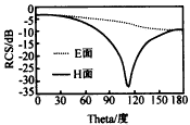
Example 1 is a certain radius of a metal conductor ball with an electrical size of ka = 0.5 is irradiated by a plane wave from the negative z direction, as shown in Figure 2. Figure 3 is the double-station RCS of the E and H planes of this example. It is the corresponding result of article [2]. Obviously, the two have a good consistency. 
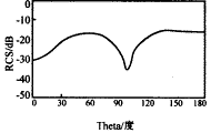
Example 2 is an infinitely thin metal conductor cylinder open at both ends irradiated by a plane wave from the negative z-direction (axial direction of the cylinder), as shown in Figure 2. Figures 5 and 7 are its E-plane and H-plane, respectively. The RCS curve of the station, the electrical size of the cylinder radius is ka = 1, and the electrical size of the cylinder length kl = λ. Compared with the data in [2] (Figure 6, Figure 8), it is very consistent. 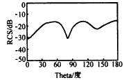

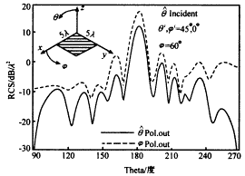
![]() Polarization and
Polarization and Polarization direction bistatic RCS calculation. The incident field is
![]() Polarization, the incident direction is (θi, φi) = (45 °, 0 °).
Polarization, the incident direction is (θi, φi) = (45 °, 0 °).
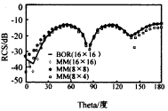
Figure 9 is the calculation result of the method in this paper, and Figure 10 is the corresponding result of article [3]. 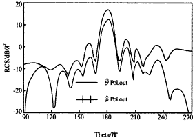
![]() The roof function of singular point is selected at the center of the finite small block (parameter space), and the size of the finite small block Δs0 needs to be able to meet R0≈R under certain accuracy conditions. Three numerical examples show that the two The method can accurately solve the singular integral in the three-dimensional vector electromagnetic scattering problem.
The roof function of singular point is selected at the center of the finite small block (parameter space), and the size of the finite small block Δs0 needs to be able to meet R0≈R under certain accuracy conditions. Three numerical examples show that the two The method can accurately solve the singular integral in the three-dimensional vector electromagnetic scattering problem.