Fiber optic adapters are typically used to connect two fiber optic cables together. They come in versions to connect single fibers together (simplex), two fibers together (duplex), or sometimes four fibers together (quad). Adapters are designed for multimode or single-mode cables. The single-mode adapters provide more precise alignment of the tips of the connectors and can be used to connect multimode cables. The reverse is not suggested as this might cause misalignment of the small single-mode fibers and loss of signal strength (attenuation).
Optical attenuators can take a number of different forms and are typically classified as fixed or variable attenuators. What's more, they can be classified as LC, SC, ST, FC, MU, etc. according to the different types of connectors.
Sijee provides different types of Optical Fiber Attenuator, Fiber Optic Attenuator, Fiber Optic Fixed Attenuator, FC Fiber Attenuator.
Fiber Optic Attenuator Optical Fiber Attenuator,Fiber Optic Attenuator,Fiber Optic Fixed Attenuator,FC Fiber Attenuator Sijee Optical Communication Technology Co.,Ltd , https://www.sijee-optical.com
Introduction Maxim's serializers and deserializers (SerDes) for LVDS signal links are ideal for video display, image acquisition, and data transmission systems in automotive and telecommunications systems. When using the SerDes chipset to transmit high-speed data, designers need to understand the performance of the SerDes link in order to determine the reliability margin of data transmission. Generally, this can be evaluated using eye diagrams or eye diagram templates for performance and margin; 1, 2 but there is no clear and convincing method for determining eye diagrams based on experimental data.
This article systematically introduces the method to determine the eye pattern template based on the measured serial link eye pattern and bit error rate. To illustrate this process, the test system uses the MAX9217 and MAX9250 SerDes chipsets to build an eye diagram and link reliability margin test system. The cables of different lengths were used in the test and tested at different temperatures (+ 25 ° C, + 95 ° C and + 105 ° C).
Note: The test results for the MAX9250 are also applicable to the MAX9248. The output of the MAX9248 is a spread spectrum parallel output. In addition, the MAX9248 and the MAX9250 have the same receiving circuit.
Test system construction The test system includes the following equipment: Agilent 86130A error code tester Agilent 83752A synthetic scanner Agilent 70820A microwave transient analyzer Agilent 3325A function generator High-quality shielded cable (model: PT1482) produced by MD Elektronik GmbH3 build MAX9217 The physical link between the serializer and the MAX9250 deserializer. This cable connects the two Rosenberger4 sockets (model: D4S20D-40ML5-Y, water blue) on the transmitter (MAX9217) side and receiver (MAX9250) side of the evaluation board. color). For detailed information / links on the Rosenberger website, see the references at the end of this application note.
The instruments and equipment required for the test system are shown in Figure 1. 
Figure 1. Experimental configuration of eye diagram template test
The bit error tester outputs a serial digital signal to the MAX9250 deserializer, and then tests the bit error rate of the serial data returned from the MAX9217. Use a cable to connect the serial output to the error analyzer and the serializer input to the MAX9250. In this test, cables and connectors produced by MD Electronik and Rosenberger are used, and all devices meet the stringent specifications of automotive applications.
This test uses PT1482 cables of different lengths (see Table 1 to Table 3 for test results). The parallel output of the MAX9250 is connected to the parallel input of the MAX9217, and the serial output of the MAX9217 is connected to the serial input of the error analyzer. In this configuration, you can use the error analyzer to test the bit error rate of the SerDes link.
The synthetic scanner generates the clock required by the error tester to output serial data; the microwave transient analyzer controls the function generator to add sinusoidal modulation at the correct time for the output clock. Equivalent to injecting jitter on the serial output of the error tester. The sinusoidal modulation frequency is 5MHz, which is about ten times the PLL loop bandwidth of the MAX9250 receiver. This option converts sinusoidal modulation to deserializer phase jitter rather than low frequency drift that can be tracked by the receiver PLL.
The bit error meter can also adjust the differential amplitude of the output data. Figures 2a and 2b show the jitter and voltage adjustment of the data output of the bit error meter. 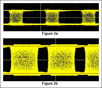
Figure 2. Comparison of test results when different jitter is injected and different signal swings are output: Figure 1a is a small signal swing and medium input jitter; Figure 2b is a conventional signal swing, injected with greater jitter
After setting the jitter and differential voltage swing, you can test the performance of the link. The rate of parallel data is 33Mbps, and the rate after serial conversion is 660Mbps; the total jitter at the input of the serializer is equal to the injected sine jitter plus the fixed jitter generated by the limited link bandwidth.
Eye diagram mask test As a measure of performance indicators, the SerDes link eye diagram template gives an understanding of the vertical and horizontal size limits of the eye diagram at the input end of the serializer. As long as the eye opening is greater than the template, the designer can be confident that the serial data transmission system is reliable.
However, there is currently no widely accepted method for eye diagram testing; the main difficulty is that the shape of the eye diagram depends on many factors: signal swing, cable characteristics, jitter, and temperature. The challenge is how to generate a reasonable eye diagram template for a given cable and temperature specification. In addition, it is also very important to eliminate the correlation between signal amplitude and jitter.
When generating an eye pattern template, you first need to observe the eye pattern of the deserializer output signal. When the signal "swing" is above the observed threshold, the performance of the deserializer depends mainly on the size of the jitter. The series of tests conducted in the experiment were based on a 5m long cable with a serial data rate of 660Mbps. For each given signal amplitude, the maximum jitter allowed by the deserializer was determined. If the deserializer has no error within 2 minutes, we can judge that the deserializer can tolerate the injected jitter. Statistically speaking, no error occurred within 2 minutes, which means that the confidence is higher than 99.9%, and the error rate of the link is lower than 10-10. Figure 3 shows the maximum acceptable jitter value for a given signal swing at + 25 ° C and + 95 ° C ambient temperature. The unit of jitter is UI (unit interval), 1 UI = 1 / 660MHz = 1.515ns. 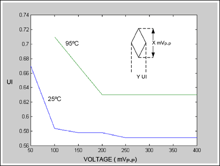
Figure 3. Acceptable jitter value for a given signal swing at two temperatures
As can be seen from Figure 3, at + 25 ° C, when the signal swing exceeds 100mVP-P, the performance has little effect; at + 95 ° C, a similar conclusion can be obtained, except that the swing threshold is 200mVP-P. Therefore, take a conservative signal swing threshold for the eye pattern template: 200mVP-P, and change the amount of injected jitter until the link fails. An appropriate template is generated in this way. When the system meets the requirements of this template, the integrity of the link signal can be guaranteed.
After measuring the eye pattern template of a given link and determining the method for generating the eye pattern template, the eye pattern template can be measured on the links at different lengths of cable and at different temperatures. In the measurement device of Figure 1, adjust the swing of the output signal so that the signal swing at the input of the deserializer is 200mVP-P, and confirm that the vertical height of the eye pattern template is 200mVP-P (the "x" value in Figure 3). The next step is to inject different jitter into the link to determine the horizontal length of the eye pattern template (the "y" value in Figure 3). The horizontal length is measured when the link has no error within two minutes when the maximum jitter is injected. Table 1 shows the horizontal length of the eye diagram template under different experimental conditions. The unit of the horizontal length is UI.
Table 1. Horizontal length of eye diagram template in UI
* Note: The 5m cable has a connector at 2.5m, and the 10m cable has three connectors placed at 2.5m, 5m, and 8m. Test Board No. 0m Cable 5m * Cable
PT1482 10m * Cable
PT1482 + 25 ° C + 25 ° C + 25 ° C 1 0.597 0.551 0.525 2 0.604 0.578 0.545 3 0.604 0.551 0.525 + 95 ° C + 95 ° C + 95 ° C 1 0.657 0.630 0.597 2 0.644 0.644 0.591 3 0.637 0.624 0.597 + 105 ° C + 105 ° C + 105 ° C 1 0.663 0.630 0.670 2 0.604 0.611 0.683 3 0.597 0.591 0.637
Figure 4 shows the eye diagrams under the two test conditions. 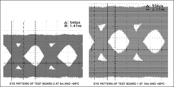
Figure 4. 200mVP-P eye diagram, maximum jitter tolerance
Note that most oscilloscope differential probes cannot withstand excessively high cabinet temperatures, so this experiment injects the same signal swing and jitter to the measurement system at room temperature to measure the eye diagram. Through experimental observation, the eye diagram at room temperature is very similar to that at high temperature: the input impedance of the deserializer is high, and the input terminal is terminated with a precision external resistor to form a 100Ω differential load to reduce the effect of temperature.
Obtaining the link reliability margin from the eye diagram template The link reliability margin can be directly derived from the eye diagram template. The conditions for measuring the eye diagram at the input of the deserializer in Figure 5 are the same as those used in Table 1, that is, the cable length and temperature are the same. 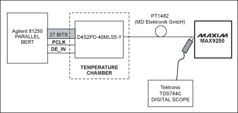
Figure 5. Eye diagram measurement device
To protect the probe from high temperature damage, place the MAX9250 deserializer outside the thermostat. Table 2 shows the 2D eye diagrams for different differential cable lengths and temperatures.
Table 2. Measurement link eye diagram Test Board No. 0m Cable 5m Cable
PT1482 10m Cable
PT1482 Eye Open (Hor., UI) Eye Open (Ver., MVP-P) Eye Open (Hor., UI) Eye Open (Ver., MVP-P) Eye Open (Hor., UI) Eye Open (Ver., MVP-P) + 25 ° C + 25 ° C + 25 ° C + 25 ° C + 25 ° C + 25 ° C 1 0.894 480 0.815 374 0.670 226 2 0.881 464 0.815 372 0.716 236 3 0.894 504 0.809 368 0.696 228 + 95 ° C + 95 ° C + 95 ° C + 95 ° C + 95 ° C + 95 ° C 1 0.815 380 0.710 220 2 0.802 388 0.723 210 3 0.842 404 0.729 248 + 105 ° C + 105 ° C + 105 ° C + 105 ° C + 105 ° C + 105 ° C 1 0.795 376 0.696 204 2 0.782 380 0.716 206 3 0.822 400 0.716 230
By comparing the eye diagram templates corresponding to Table 2 and Table 1, the reliability margin of each link can be obtained. As shown in Table 3, the margin in the vertical direction is expressed in dB, and the horizontal direction is expressed in UI.
Table 3. Eye diagram margins for different cable lengths and temperatures Test Board No. 0m Cable 5m Cable
PT1482 10m Cable
PT1482 Eye Margin (Hor., UI) Eye Margin (Ver., DB) Eye Margin (Hor., UI) Eye Margin (Ver., DB) Eye Margin (Hor., UI) Eye Margin (Ver., DB) + 25 ° C + 25 ° C + 25 ° C + 25 ° C + 25 ° C + 25 ° C 1 0.297 7.6 0.264 5.4 0.145 1.1 2 0.277 7.3 0.238 5.4 0.172 1.4 3 0.290 8.0 0.257 5.3 0.172 1.1 + 95 ° C + 95 ° C + 95 ° C + 95 ° C + 95 ° C + 95 ° C 1 0.185 5.6 0.112 0.8 2 0.158 5.8 0.132 0.4 3 0.218 6.1 0.132 1.9 + 105 ° C + 105 ° C + 105 ° C + 105 ° C + 105 ° C + 105 ° C 1 0.165 5.5 0.026 0.2 2 0.172 5.6 0.033 0.3 3 0.231 6.0 0.079 1.2
Embedded eye diagram templates can be visually compared in the eye diagram, as shown in Figure 6. 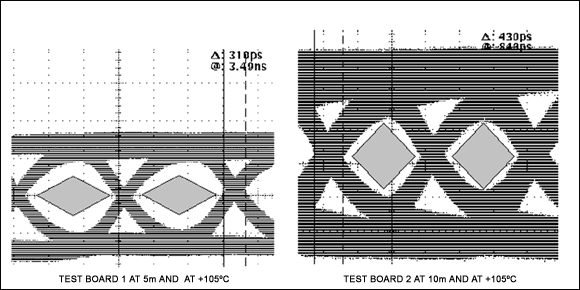
Figure 6. Eye diagram template embedded in test eye diagram
The following conclusions can be drawn from Table 3: The eye diagram template is affected by many factors: such as cable type, cable length, connector type, temperature, data rate, and the difference between chips.
When the cable length is 5m, the MAX9217 / MAX9250 SerDes chipset can provide sufficient reliability margins in the vertical and horizontal directions at a data rate of 660Mbps.
When the cable length is 10m, the reliability margin of the MAX9217 / MAX9250 SerDes chipset in both directions is not large.
In Test 1, the vertical height estimation of the eye template is conservative (refer to Table 1). If the signal swing threshold at room temperature is 100mVP-P, you can get a lower opening eye mask and a larger vertical margin. Conclusion In this paper, the eye diagram template of SerDes chipset is generated by the experimental method. Since the signal swing has a small impact on link performance when it reaches a certain threshold amplitude, this method eliminates the effect of signal swing on jitter tolerance. The test system uses this threshold as the vertical opening of the eye pattern template and the maximum jitter tolerance as the horizontal size of the template. The obtained eye pattern template can be used to evaluate the reliability margin of the link.
A similar article was published in the October 2008 issue of ECN.
References Agilent, Inc., ApplicaTIon note, "Calibrated Jitter, Jitter Tolerance Test and Jitter Laboratory with the Agilent J-BERT N4903A," at: http://cp.literature.agilent.com/litweb/pdf/5989-4967EN .pdf Agilent, Inc., White Paper, "Comparison of Different Jitter Analysis Techniques with a Precision Jitter Transmitter," at: http://cp.literature.agilent.com/litweb/pdf/5989-3205EN.pdf MD Elektronik GmbH , PT1482 cable informaTIon at: http: // Rosenberger, Inc., Technical Data Sheet for Right Angle PCB Plug, D4S20D-40ML5-Y at: http: //D4S20D-40ML5-Y.pdf.
Optical attenuators are commonly used in fiber-optic communications, either to test power level margins by temporarily adding a calibrated amount of signal loss, or installed permanently to properly match transmitter and receiver levels. Sharp bends stress optic fibers and can cause losses. If a received signal is too strong a temporary fix is to wrap the cable around a pencil until the desired level of attenuation is achieved. However, such arrangements are unreliable, since the stressed fiber tends to break over time.
Types:
Evaluation of serializer and deserializer (SerDes) performance using eye diagram templates
Abstract: Maxim has developed a series of serializers and deserializers, which are widely used in high-speed, serial data interconnection in video display and digital image systems. Currently, designers urgently need to find a way to test the performance and margin of serial data links built by serializer and deserializer (SerDes) chipsets. This paper presents a test plan, first measuring the eye diagram template of the serial link, and then deriving the indicator margin based on the template.