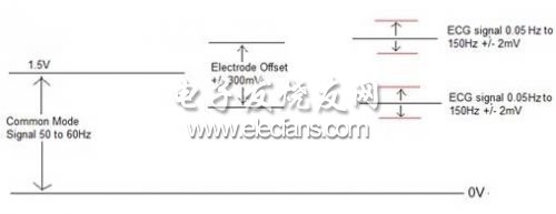
An electrocardiogram (ECG) is used to capture the reflection of the heart's condition over a period of time. It is connected to the skin through external electrodes and converted into electrical signals for collection. Each cell membrane formed outside the heart has an associated charge, which depolarizes during each heartbeat. It appears on the skin in the form of tiny electrical signals, which can be detected and enlarged by electrocardiogram. As early as 1900, Willem Einthoven invented the first practical electrocardiogram. The system is bulky and requires many people to manipulate it. The patient needs to place his arms and legs in a large electrode containing electrolyte. Today's ECG monitoring equipment is compact and easy to carry, so that patients can also carry it when they are walking. A twelve-lead ECG for home use can be carried in a pocket. ECG basics: The term "lead" on the electrocardiogram in this article refers to the voltage difference between the two electrodes, which is the difference recorded by the device. For example, "Lead_I" is the voltage between the left and right arm electrodes. Both Lead_I and Lead_II refer to limb leads. V1-V6 refers to the chest leads. ECG tracking V1 is the difference between the Vc1 voltage (the voltage of the chest electrode), and the average voltage of Lead_I, Lead_II, and Lead_III. A standard 12-lead ECG system includes eight real values ​​and four derived values. Table 1 gives a brief description of the various lead voltages (real and derived). Lead name calculation notes This is a real lead, shown in the ECG trace. Table 1: Lead names and ECG recording locations. A typical ECG waveform is shown in Figure 1. The X axis represents the time scale. Here, each grid (5 mm) corresponds to 20 ms. The Y axis shows the amplitude of the captured signal. Each division (5 mm) on the Y axis corresponds to 0.5 mV. (10mm / mV and 25mm / s) Figure 1: Typical ECG waveform. ECG features: The first step in the design of an ECG system includes understanding the types of signals that need to be acquired. The electrocardiogram signal includes a low-amplitude voltage present in high bias and noise. Figure 2 shows the characteristics of the ECG signal. There is a high offset in the system due to the half-cell voltage produced by the electrodes. Ag / AgCl (silver-silver chloride) is the most common electrode in an electrocardiogram system, and its maximum offset voltage is +/- 300mV. The actual expected signal is +/- 0.5mV superimposed on the electrode offset. In addition, the system will also close up the 50 / 60Hz noise from the power line to form a common mode signal. The amplitude of power line noise may be very large and it needs to be filtered. Figure 2: The characteristics of the ECG signal to be obtained. ECG acquisition Analog front-end processing is an important part of the ECG system because it needs to distinguish between noise and the desired signal (the amplitude is small). The analog front-end processing circuit includes a measurement amplifier to reduce the signal in normal mode. The measurement amplifier works at +/- 5V and is usually used to increase the input voltage range. This measurement amplifier should have a high input impedance because the impedance of the skin can be very large. An op amp is required for signal processing of the electrocardiogram device. The signal chain of the ECG acquisition system includes measurement amplifiers, filters (which can be implemented by op amps) and ADCs.
Universal input voltage 90~305Vac; Constant voltage design; Active power
factor correction; High power factor > 0.96; Multiple protection: SCP, OVP,
OTP, OLP; Surge protection: 35W/50W: line-line 4KV, line-earth 6KV 75~320W:
Line-line 5KV, line-earth 10KV; Degrees of protection: IP67; Ambient
temperature: -40℃~+60℃; 5 years warranty.
The wattage: 35W/50W/75W/100W/150W/200W/320W.
The output voltage: 12V/24V/36V/48V.
The LED power supply got global safety certifications, including UL, CE,
TUV, CB, SAA etc. The LED control gear has universal input voltage, from
90~305Vac. It is a reliable product compatible with various landscape application
and different countries.
Due to the high IP rating, the LED driver can be used for dry, damp, wet
locations. It is suitable for installing outside of the fixture. The
perfect cooling design can ensure the product reliability and long lifetime for
at least 10 years (50,000hours operation at least) minimum.
Constant Voltage LED Driver Constant Voltage LED Driver,Constant Voltage Driver,12V LED Driver,24V LED Driver Moso Electronics , https://www.mosoleddriver.com