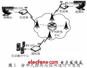
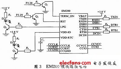
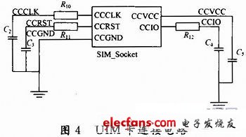
Aiming at the use requirements of the detection station and the fusion center under various geographical environments and vehicle moving conditions, a CDMA real-time transceiver system based on the EM200 module was constructed. Compared with the traditional long-distance wireless communication GPRS system, the CDMA system is superior to GPRS in stability and bandwidth, and is more suitable for a distributed information fusion system with strict delay requirements. 1 System architecture As shown in Figure 1, the distributed detection network consists of transceiver terminals and intermediate forwarding platforms. The sending end receives the data from the detection station via the RS 232 port and sends it out through the CDMA network. The receiving end sends the data received from the CDMA network to the information fusion center. In view of the reliability requirements of communication, the system all uses TCP communication protocol, and the sending and receiving terminals are used as TCP clients, and the intermediate forwarding platform on the public network is used as the TCP server to realize data exchange between the sending and receiving ends. 2 Communication terminal hardware design 2.1 Basic framework of the hardware of the transceiver Figure 2 lists the basic hardware block diagram of the communication terminal, which is mainly divided into power supply module, microcontroller (MCU) and its supporting units, CDMA module and other auxiliary units. The hardware structure of the transceiver is exactly the same. At present, the serial port is still one of the most versatile interfaces. Most wireless communication modules communicate serially with the outside world through the serial port, as does the EM200. The MCULPC22 14 selected here has two sets of serial ports, and serial port 0 is assigned as the transceiver to exchange data with the outside world (the sending end receives data from the detection station via serial port 0, and the receiving terminal sends data to the fusion center via serial port 0), serial port 1 Used as a communication interface between the microcontroller and EM200. 2.2 EM200 related circuit design The circuit design related to the EM200 module is listed here. Figure 3 is the main circuit of the EM200 module, in which the LPG pin and the VDD-IO pin drive LEDs through a transistor to indicate the module's working status. The external start and restart module signal pins also drive the EM200 through the transistor. Figure 4 shows the connection circuit between the module and the UIM card. The 33 pF capacitor is used to filter the interference generated by the RF circuit. At present, most ARM7s have more than two sets of serial ports, of which there is usually a set of serial ports with a complete modem interface, such as LPC2214. LPC2214 as DTE (data terminal equipment) is connected to EM200 as DEC (data communication equipment) through serial port 1. It should be noted that the connection between DTE and DCE does not require cross TXD / RXD lines. Cat6 Network Cable,Cat6 Utp Shield Network Cables,Ftp Cat6A Network Cable,Cat 6 Ethernet Cable Dongguan Fangbei Electronic Co.,Ltd , https://www.connectorfb.com