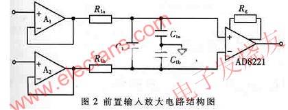
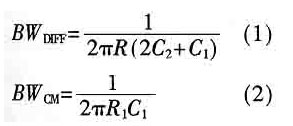
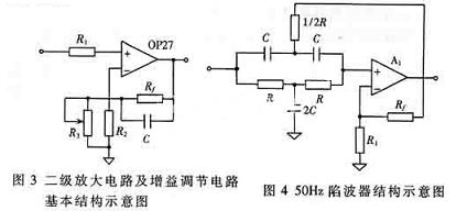
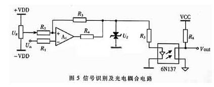
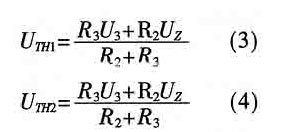
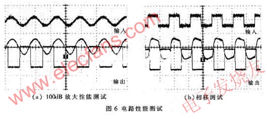
The neural signals of the human body directly represent the meaning of the human self, and studying neural signals provides a way to understand and identify the human body. Over the years. At present, the research content mainly includes two parts: nerve electrode and nerve signal conditioning circuit. The nerve electrode can extract the nerve electrical signal from the human body, and the nerve signal conditioning circuit performs denoising, amplification, and recognition processing on the nerve signal. Neural signals have the same characteristics as other biological signals of the human body, and also have some unique characteristics. According to the research of neurobiology, a neural signal is an electrical signal that looks like a pulse. The frequency is generally about 1kHz, and the high one can reach 10kHz. For example, a bunch of motor nerves that control muscles. When an impulse potential signal arrives, the muscle fibers will undergo a contraction reaction. The strength of the contraction varies according to the frequency of nerve impulses. Therefore, as long as the pulse potential is identified and processed into a digital control signal, a specific application such as prosthesis control can be performed. Of course, the detection of neural signals also has its difficulties. The human body's neural signals are low-frequency weak signals under strong noise interference. Because they are very weak, only a microvolt level, and the interference is extremely powerful, the effective signal is often overwhelmed. Interference signals generally include high-frequency electromagnetic interference, 50Hz power frequency interference and polarized voltage. Power frequency interference mainly exists in the form of common-mode signals, usually with amplitudes up to several volts to tens of volts. The polarization voltage is the DC voltage generated by the chemical half-cell formed between the measured electrode and the biological tissue. It is generally several tens of millivolts and can reach a maximum of 300mV. In addition, due to the complexity and particularity of the organism, its equivalent signal source output impedance is generally very large, which can be several tens of thousands of ohms, which must also be considered. According to the above description of the characteristics of neural signals, a highly targeted, superior performance, stable and reliable neural signal conditioning circuit is designed. 1 Circuit system structure and principle According to the characteristics of nerve signals and the characteristics of general electrodes, the conditioning circuit must have some necessary performance. First, the circuit must have a very high common-mode rejection ratio, which suppresses power-frequency interference and interference from physiological effects other than measurement parameters. If the common-mode rejection ratio of the circuit is 120dB, the effect of the common-mode signal in the input signal will be reduced by 1 million times, and the 1V common-mode signal will have a 1μV differential-mode signal. At the same time, the input impedance of the circuit is also a very important parameter. The high input impedance can effectively reduce the influence of the high internal resistance of the signal source. The output impedance of the equivalent signal source of the organism mentioned above can generally be several tens of thousands of ohms, which requires the input impedance of the designed circuit to be greater than 100 megaohms. In addition, due to the different body tissues contacted by each electrode, it exhibits an unstable high internal resistance source property, which will cause an imbalance in the input impedance of the electrode and convert common mode interference to differential mode interference. Increasing the input impedance of the amplifier helps reduce the impact of this conversion. At the same time, relative to neural signals with amplitudes of microvolts, the indicators such as low noise and low drift of the conditioning circuit are also extremely important. The structure of the neural signal conditioning circuit proposed in this paper is shown in Figure 1. The circuit system is divided into three parts: pre-input amplifier circuit, intermediate-level signal processing circuit and subsequent signal recognition transmission circuit. 2 Circuit design Early biological signal circuits mostly used discrete component designs. With the continuous development of microelectronic technology, many high-performance integrated instrument amplifiers have appeared. Due to the excellent performance of such devices, installation and debugging work have been avoided. China has been generally welcomed. This type of device is fully used in the design of this article. 2.1 Front input amplifier circuit The prestage mainly considers the effects of noise, input impedance and common mode rejection ratio. The circuit designed here consists of three parts: input buffer, high frequency filtering and instrumentation amplifier. The circuit structure diagram is shown as in Fig. 2. Since the input buffer adopts a direct voltage negative feedback design, the theoretical input impedance is infinite, which effectively isolates the human body from the circuit system and removes the effects of high and unstable internal resistance of the signal source. The low-pass filter network composed of R1a, R1b, C1b, and C2 can effectively remove the influence of high-frequency electromagnetic noise. The differential mode signal cutoff frequency BWDDFF and common mode signal cutoff frequency BWCM of the circuit are shown in equations (1) and (2), where R1a, R1b, C1a, and C1b must be exactly equal, and C2> 10C1. Generally speaking, instrumentation amplifiers have no common-mode rejection capability for signals higher than 20kHz. The use of this network can make instrumentation amplifiers work more efficiently. Because of its classic three-op-amp structure, instrument amplifiers have high input impedance and common-mode rejection ratio, and only need to connect an external resistor to set the gain, which is widely used in the field of biological signal processing. The AD8221 of the AD company selected here is the latest model, which is an order of magnitude higher than the general-purpose AD620 in all aspects. In addition, due to the existence of polarization voltage, in order to avoid saturation of the circuit, the gain of the pre-amplifier circuit must be within tens of times, not too large. 2.2 Intermediate processing circuit The intermediate-stage processing circuit is divided into a band-pass frequency selection network, a second-stage amplifier circuit, a 50Hz trap, and a gain adjustment circuit. The band-pass frequency selection network is composed of RC passive network, which is simple and reliable. The maximum range of the pass band is set to 0.05Hz ~ 10kHz. According to individual differences, the network can be selected by the digital control circuit by combining different frequency bands to meet the best signal state. The structure of the two-stage amplifying circuit is similar to that of the gain adjusting circuit, and they are all connected into a form of voltage negative feedback by the operational amplifier. The former amplifies the signal, while the latter controls the gain of the overall circuit, up to 120dB. The schematic diagram of its structure is shown in Figure 3. Here, OP27 is selected for the operational amplifier, and a voltage series negative feedback structure is used. The advantage is that the structure is simple, and it has the following irreplaceable superior performance: (1) The input equivalent impedance is large, Ri = (1 + AF) rid, the output equivalent impedance is small, Ro = ro / (1 + AF), where , Rid is the input impedance of the op amp, ro is the output impedance. It not only completes the signal amplification, but also acts as a buffer, effectively isolating the modules at the front and rear stages, without adding additional impedance converters and matching modules; (2) The use of capacitor C makes the entire module have a low pass The function can not only remove the high-frequency interference in the signal, but also compensate the phase of the high-frequency part of the effective signal due to its advanced compensation. Through reasonable design, the phase of the circuit frequency section will change smoothly. The neural signal mentioned above is a kind of pulse-like signal, and the signal shape is not significantly distorted, which has a positive meaning when it is processed in the time domain. The 50Hz power frequency trap uses a typical active dual-T notch network scheme, with Q = 2.5, which can effectively remove power frequency interference in the signal. Its structure diagram is shown in Figure 4. 2.3 Signal recognition and photoelectric coupling circuit The nerve signal is a pulse-like analog electrical signal. Before transmitting this signal to the subsequent digital circuit, it needs to be regularized into a standard square wave signal. This is done by the signal recognition circuit, which consists of a hysteretic comparator. In order to ensure safety and prevent interference between analog and digital circuits, the photoelectric isolation circuit is also an indispensable module. The signal identification and photoelectric coupling circuit are shown in Figure 5. The hysteresis comparison circuit is a signal feedback structure consisting of an op amp. It has strong anti-interference ability. The threshold can be adjusted by UR according to the actual situation. The threshold of the circuit is given by equations (3) and (4). In addition, because the effective frequency of the signal can reach 10kHz, the speed of the photocoupler is an important index, and the 6N137 photocoupler is selected here. 3 Results and discussion After the circuit debugging is completed, a standard signal is generated by the function generator to perform a series of performance tests on the circuit. From the above discussion, it can be seen that the neural signal is a weak analog electrical signal like a pulse, so the amplification performance and phase shift characteristics of the circuit are the focus of the test. Fig. 6 (a) and (b) are the results of signal amplification performance and phase shift test respectively. The function generator generates a 500mV / 1kHz sinusoidal standard signal. After 40dB attenuation twice, a 50μV / 1kHz test input signal is obtained to test the amplification performance. It can be seen from the figure that the circuit effectively amplifies the signal by 100dB. The phase shift test is performed by a 1kHz square wave simulated neural signal generated by a function generator. If the phase shift of the signal in each frequency band of the system is significantly different, it is very easy to cause distortion of the signal shape. It is very unfavorable to perform time-domain processing on the signal. From the results, except that the high-frequency components in the signal are not filtered in the effective frequency band, the overall phase shift of the signal is stable, maintaining the original shape, and can be fully valued in the time domain after recognition and regulation. From the above discussion, we can see that the circuit proposed in this paper effectively solves the problem of neural signal conditioning, and the circuit system solves the problem of neural signal conditioning. The circuit system is practical and reliable. At present, the research on implantable electrodes that can extract nerve signals has been completed, and the use of the circuits in the article will continue to carry out clinical trials and other research work.
The LED Indicator is a device that monitors the operation or position of an electrical device with light. The indicator light is usually used to reflect the working state of the circuit (with or without electricity), the operating state (running, outage or test) of the electrical equipment, and the position status (closed or disconnected).
In our company,mainly have eight series(as follow):
AD22-22DS LED Indicator
LED Indicators,LED Indicator Light,LED Indicator Lamp,LED Indicator Bulbs Ningbo Bond Industrial Electric Co., Ltd. , https://www.bondelectro.com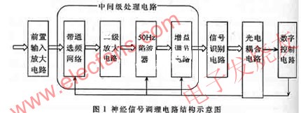
AD16 LED Indicator
AD22-22MSD Buzzer
AD22-30DS LED Indicator
AD22-DAV Current Voltage Indicator
AD22-DAM Current Indicator
AD22-DVM Voltage Indicator