CNC system control software and its working process 2. Decoding From the previous discussion, we can see that after the work of the input system, the data segment has been sent to the part program memory. The next step is to translate the input part program data segment into a language that the system can recognize by the decoding program. A data segment needs to go through the following links from input to transmission to the interpolation working register, as shown in Figure 3-17. Figure 3-18 Decoding program flowchart Figure 3-25 Front and background structure The characteristic of the interrupt type structure is that, in addition to the initialization program, all the various task modules in the system software are arranged in different levels of interrupt service programs. The entire software is a large interrupt system. Its management function is mainly solved by mutual communication between the interrupt programs at all levels.
Deluxe
Rice Cooker was one of electric type rice cooker , but it`s the most popular type of electric
rice cooker . especially famous in Southeast Asia area with its good
appearances with various functions. Not only its outer shell could be
customized with different demands, but also it speeding cooking , saving times and electricity, enhancing our
lifestyle
Features
The
inner pot is made of solid and durable aluminum alloy of high intensity , such as non-stick inner pot , stainless
steel inner pot and honeycomb patterned inner pot with non-stick coating.
There are some models that use stainless steel instead of
aluminium .Various other materials, such
as copper, pure carbon, ceramic, and diamond powder coating, may be used for
higher heat conductivity or better taste.
Applications
Multifunction , can cooking rice, soup and much
more. added cooking versatility with supplied steam tray.
Some rice cookers have settings for congee, a type of
rice porridge called okayu in
Japanese, Juk in Korea, and zhou in Chinese.
More elaborate recipes are possible using a rice cooker, and there
are cookbooks devoted entirely to dishes prepared using a rice cooker. It is possible to cook soups, stews or
sponge cakes in electric rice cookers. By
simply adding ingredients and setting it to "warm", a rice cooker
cooks the contents at about 65 °C (150 °F). In a few hours, the stew is fully
cooked and ready to eat.
Deluxe Rice Cooker Deluxe Rice Cooker,Cylinder Rice Cooker,Mini Rice Cooker,Stainless Steel Rice Cooker Guangzhou Taipeng Electrical Appliances Technology CO., LTD. , https://www.taipengelectric.com
Control software is special software compiled for the completion of various functions of a specific CNC (or MNC) system, also known as system software (or system program). Because the function settings and control schemes of CNC (or MNC) systems are different, various system softwares vary greatly in structure and scale. The design of the system program has the most direct relationship with the realization of each function and its future expansion. It is the most critical and the most workload part of the entire CNC (or MNC) system development work.
As mentioned earlier, the system software is generally composed of input, decoding, data processing (pre-calculation), interpolation calculation, speed control, output control, management program and diagnostic program. The following are introduced separately.
1. Enter
In CNC systems, part programs are generally input through paper tape readers, tape drives, magnetic disks, and keyboards, and most of their input is interrupted. There are corresponding interrupt service routines in the system program, such as paper tape reader interrupt service routine and keyboard interrupt service routine. When the paper tape reader reads a character into the interface, it sends an interrupt to the host, and the interrupt service program sends the character into the memory. In the same way, each press of a key means applying for an interrupt to the host, calling up a keyboard service program, and processing the corresponding keyboard commands.
The part program input from the reader and the keyboard usually enters the part program memory after passing through the buffer. The size of the part program memory is determined by the system designer. Generally, there are several kilobytes, which can store many part programs. For example, the part program memory of the 7360 system is 5K, which can store more than 20 part programs.
The keyboard interrupt service program is responsible for storing the characters entered on the keyboard into the MDI buffer, and pressing the button applies to the host for an interrupt. The block diagram is shown in Figure 3-16. 
Figure 3-16 Keyboard interrupt service routine 
Figure 3-17 The process of a data segment From the principle and essence, software decoding is the same as hardware decoding. For the 8-unit paper tape program, one character occupies 8 bits. In a 16-bit word-length buffer, one word can store two characters. The longer the data segment, the greater the number of words. The decoding program compares each character with the corresponding number in order. If they are equal, it means that the character has been entered. It is like in the hardware decoding circuit, when a code is input, only the corresponding AND gate is opened. The difference is that the decoding program works serially, that is, it compares one by one until it is equal. The hardware decoding circuit works in parallel, so the speed is faster. Taking ISO code as an example, M is
, Ie M is octal
, S is
, T is
, F is
, ..., therefore, when determining whether the M, S, T or F words have been programmed in the data segment, you can compare the entered characters with these octal numbers, if they are equal, it means that the corresponding characters have been entered, Set up the corresponding mark immediately.
The processing process after a certain character input includes:
(1) Establish a format sign. If it is a bit format, the number of format words occupied by each character is different.
(2) According to the different input characters, determine the corresponding address to store the value. For example, the value of the M code is stored at 1000H, and the value of the S code is stored at 1002H, ...; some systems have specific address codes (such as N,
X, Y, G, M, F, etc.) have a displacement in the storage area. The first address of the area plus the displacement corresponding to the address code can get the area where the address code is stored.
(3) Determine the number of times to call the "digital conversion program". After a code, there are always numbers connected, such as M02, S11, X1000000, .... The value of the M code is at most 2 digits, the code is at most 2 digits (or 3 digits), and the value of the X code is at most 7 digits. Each system is different. But for a specific system, there is a specified value. If a certain code is worth up to 2 digits, then only need to call the digital conversion program twice. The so-called digital conversion is to convert the input characters (such as ASCII code) into binary code and store it in the memory.
An information table is required to combine processor programs of different characters. None of the characters in this table has a corresponding column. The content in the column includes the address offset, the number of digits in the format flag and the number of times the digital conversion program is called. After one arithmetic and logical operation, the decoding can be completed. While decoding, the system must check the syntax of the part program, such as whether the number of input digits is greater than the allowable value, and whether the address code with a negative sign is not allowed with a negative sign.
The decoding result is stored in the specified storage area, and the place where the decoding result is stored is called the decoding result memory. The decoding result memory stores the value of each code (binary) in a prescribed order, and includes a program format marking unit, in which a certain bit is 1, which means the specified code (such as F, S, M ... …) Has been compiled. For ease of use, sometimes a flag is created for each value or several values ​​of the G code and M code. For example, create a flag word for G00, G01, G02, G03 about the interpolation method. When the flag word is 0, it means that G00 has been programmed, and when it is 1, it means that bitch has been entered into G01 ... 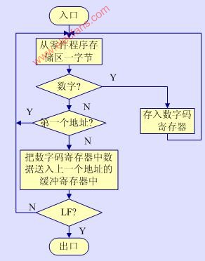
3. Pre-calculation In order to reduce the burden of the interpolation work and improve the real-time processing capability of the system, data pre-processing is often performed before the interpolation operation, for example, to determine the arc plane and the calculation of tool radius compensation. When the digital integration method is used, left-shift normalization processing and calculation of integration times can be performed in advance, so that the most direct and convenient form of data can be provided to the interpolation operation.
Data preprocessing is pre-calculation, usually including tool length compensation, tool radius compensation calculation, quadrant and feed direction judgment, feed speed conversion and machine tool auxiliary function judgment, etc. In the second chapter, the calculation method of tool radius compensation has been introduced. Only the speed calculation and control are described below.
The control method of feed rate is related to the interpolation algorithm adopted by the system, and it is also different for different servo systems. In the open-loop system, the reference pulse interpolation method is often used. The speed of the coordinate axis is controlled by controlling the frequency of the interpolation operation, and then the frequency of the pulse output to the stepper motor. The speed calculation method is based on Program the F value to determine this frequency value. There are usually two kinds of program delay method and interrupt method.
(1) Program delay method. The program delay method is also called the program timing method. This method first calculates the time interval between two interpolation operations according to the feed frequency required by the system, and uses the CPU to execute a delay subroutine to control the time between two interpolations. The feed rate can be changed by changing the cycle number of the delay subroutine.
(2) Interrupt method. The interrupt method, or clock interrupt method, refers to sending an interrupt request to the CPU every specified time, performing an interpolation operation in the interrupt service program, and issuing a feed pulse. Therefore, changing the frequency of the interrupt request signal is equivalent to changing the feed rate. The interrupt request signal can be generated by the pulse signal set by the F command or by the programmable counter / timer. If Z80CTC is used as the timer, the time constant is set by the program, and every time the timer expires, an interrupt request signal is sent to the CPU to change the time constant
You can change the frequency of the interrupt request pulse signal. Therefore, the key to the calculation and control of feed rate is how to give the time constant of CTC
.
In semi-closed-loop and closed-loop systems, the idea of ​​time division is used, and the contour curve is divided into sampling periods according to the programmed feed speed F value, that is, the iterative period of the feed-contour step size. The task of speed calculation is: when linear interpolation, calculate the step length of each coordinate axis sampling period; when interpolating an arc, calculate the step size distribution coefficient for the interpolation program (sometimes called angular step distance) ). In addition, in the feed speed control, there is generally a process of speed up, constant speed (uniform speed) and speed down to adapt to the working state of the servo system and ensure the stability of the work. This content will be introduced in detail in Chapter 5.
4. Interpolation calculation Interpolation calculation is one of the most important calculations in CNC system. In the traditional NC device, a hardware circuit (interpolator) is used to implement interpolation of various trajectories. In order to calculate the required interpolation trajectory in the software system, these digital circuits must be simulated by a computer program. The problem of using software to simulate a hardware circuit is that a system with three or more axes has three or more hardware circuits (such as a digital integrator per axis), and the computer uses several instructions to implement interpolation of. However, it takes a certain amount of time for the computer to execute each instruction. At present, the calculation speed of some small or microcomputers is difficult to meet the requirements of NC machine tools for feed speed and sub-frequency. Therefore, in the actual CNC system, the method of combining rough and fine interpolation is often used, that is, the interpolation function atmosphere software interpolation and hardware interpolation are two parts. The computer control software divides the tool path into several segments, and the hardware The circuit then "densifies" the data between the start and end points of the segment, so that the tool path is within the allowable error, that is, the software implements the initial interpolation and the hardware implements the fine interpolation. The following uses three-coordinate linear interpolation as an example.
5. Output The functions of the output program are:
(1) Perform servo control. As mentioned above.
(2) When the feed pulse changes direction, backlash compensation processing is required. If an axis changes from positive to negative motion, Q positive pulses are output before the reverse direction; conversely, if it changes from negative to positive motion, Q negative pulses (Q It is the backlash value, which can be preset by the program).
(3) Perform lead screw pitch compensation. When the system has an absolute zero point, the software can display the absolute coordinate value of the tool at any position. If the accuracy of each point of the machine tool is measured in advance, the error curve is made, and then the correction amount of each point is made into a table and stored in the memory of the CNC system. In this way, the CNC system can automatically compensate the coordinate position of each point during the operation, thereby improving the accuracy of the machine tool.
(4) Output of auxiliary functions such as M, S and T. In some blocks, it is necessary to start the machine tool spindle, change the spindle speed, and change the tool. Therefore, M, S, and T codes are output. Most of these codes are on and off control and are executed by the machine tool. But which auxiliary functions are executed after interpolation output, and which auxiliary functions must be executed before interpolation output, need to be confirmed before software design.
6. Management and diagnostic software Generally, the management software in the CNC (MNC) system involves only two items, namely CPU management and external device management. Since the processing of CNC machine tools is based on a single part, a part program can be divided into several program segments. The execution of each block is divided into steps such as data analysis, operation, knife control, and other motion control. Usually, these processing steps are mostly in a sequence relationship, so the actual process is the repeated execution of these predetermined steps. In the actual system, usually a main program is used to connect the entire processing process. After the main control program analyzes and judges the input data, it transfers to the corresponding subprogram for processing. After processing, it returns to the analysis, judgment, Operation ... When the main control program is idle (such as a delay), you can arrange the CPU to execute a preventive diagnostic program, or pre-process input data that has not yet been executed.
In the CNC system, the interrupt processing part is the focus, and the workload is also relatively large. Because most of the real-time control steps such as interpolation calculation, speed control, fault handling, etc. must be completed by interrupt processing. Some machine tools divide travel overtravel, alarm, reader request, interpolation, etc. into multi-level interrupts, and determine the order of response according to their priority. Some machine tools only set up a first-level interrupt. Only when the interrupt request exists at the same time, a sequence is determined by the method of hardware queuing or software query.
For a single CPU numerical control system, there are two common software structures, namely the front and background type and interrupt type.
In the CNC system of the front and background structure, the entire control software is divided into a foreground program and a background program. The foreground program is a real-time interrupt service program, which almost assumes all real-time functions, such as interpolation, position control, machine tool related logic and monitoring. The background program refers to a program that realizes input, decoding, data processing, and management functions, also known as a background program, as shown in Figure 3-25. The background program is a cyclic running program,
In the course of its operation, the real-time interrupt program at the front desk is continuously inserted and cooperates with the background program to complete the processing tasks of the parts. 
Being able to easily set up various diagnostic programs is also one of the characteristics of CNC and MNC systems. With a more complete diagnostic program can prevent the occurrence or expansion of faults. After the fault occurs, the type and location of the fault can be quickly identified to reduce the downtime of the fault. Various CNC (MNC) systems also have very different settings for diagnostic procedures. The diagnostic program may include inspection and diagnosis during the operation of the system; it may also be used as a service program to perform diagnosis before the system runs or after the fault is shut down to find the location of the fault. The CNC systems of some foreign companies can also perform communication (overseas) diagnosis. The communication diagnosis center instructs the system or the operator to perform certain test runs to find hidden troubles or faulty parts.
(1) Diagnosis during operation. The ordinary NC system already contains the buds of diagnosis during operation, such as horizontal and vertical (horizontal and vertical) parity check during paper tape input, synchronization hole loss check, illegal instruction code check, etc. In addition, there are measures such as overtravel alarm. It is more convenient to do these tasks in CNC and MNC systems. And you can also use the typewriter to indicate the diagnosis results of various items and the fault location indicated by a unified number. In general, the diagnostic programs in operation are relatively scattered, and are often included in the main control program and interrupt handler branch. Common methods are:
â‘ Use code and check memory: This method can only check those invariable areas in the program, and it must be done after restoring the initial state of the system program.
â‘¡ Format check: This method is generally used in paper tape input to check the part processing source program, including parity check, illegal instruction code (instruction code not used in this system), data overrun, etc.
â‘¢ Two-way transmission data verification: This method is commonly used in indirect CNC systems or group control systems. Manual data input can also be verified by this method.
â‘£ Check list: use the equipped printing equipment to print the program list and some intermediate data to comprehensively diagnose the failure of the host, interface and software.
(2) Shutdown diagnosis. Shutdown diagnosis refers to the use of a computer for diagnosis before the system starts to operate, or after a failure (including a precursor to the failure) of the system stops. It generally uses software control to perform phased operations, such as transferring data or simulating single control actions. Check the function of the hardware circuit item by item, and selectively find the fault location. This diagnostic program can be separated from the running system program, and then input into the computer when the diagnosis is required. If necessary, some system programs can also be flushed out and loaded into memory.
(3) Communication diagnosis. Communication diagnosis is that the user contacts the communication diagnosis center through the telephone line, and the computer of the center sends the diagnosis program to the user's computer. The program instructs the CNC system to perform a certain operation, and at the same time collects data and analyzes the system status. Compare the system status with the stored working status and even some limit parameters to determine whether the system's working status is normal, the location of the fault and the trend of the fault. It can be seen that communication diagnosis can be used both as a tool for diagnosing abnormal conditions and as a means for preventive maintenance. Because the transoceanic telephone system can be used between the user and the communication diagnosis center, it is also called overseas diagnosis.