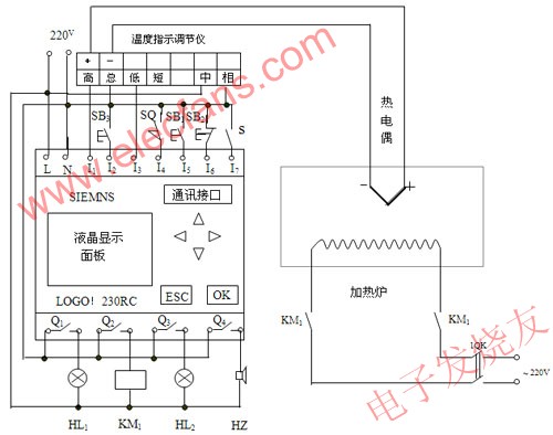
1. LOGO! Performance and characteristics LOGO! Is a general logic control module launched by SIEMENS, which is an ultra-small programmable controller that integrates a programmer and a host. LOGO internally integrates: control function, operation and display unit. There is an interface for expansion modules, an interface for program modules and PC cables. Prefabricated with basic functions, soft switches, binary indicators, inputs and outputs. Users can directly program, edit, read data or enter data through the buttons on the controller panel; can be networked with the computer and programmed with special software provided by the manufacturer. The main features of SIEMENS LOGO! Are as follows: ①Programming operation is simple. LOGO! Programming can be operated directly on this machine. ② The programming language is simple. The programming is to connect the function blocks corresponding to the functions to be realized. ③ The output current is large. LOGO! Output can withstand current up to 10A (relay output, resistive load) ④ Comes with display panel. The parameters can be set, changed and displayed directly on the built-in panel. ⑤ With communication function. LOGO! With AS-I bus function can be used as a remote I / O. ⑥ Low price. Has a lower price and higher cost performance. ⑦ Facing the public and user convenience. LOGO! Does not require special training, as long as you understand some electrical knowledge. ⑧ The volume is "small" (the volume is about 72mm * 90mm * 53mm). 2. The structure and principle of LOGO! The panel structure of LOGO! Is shown in Figure 1. The power terminal is used to connect the Power Supply (voltage 24V DC, 115V AC or 230V AC), the digital input terminal is directly connected to switches, buttons and sensors, etc. The digital output terminal is available The switch with a capacity of 8 / 10A is used to control the load. The LCD display panel allows all steps and integrated basic functions (such as logic operations and set values) and special functions (such as; timers and counters) after LOGO! Enters the control program. And clock, etc.) are displayed as functional block diagrams. During operation, the switch status of the I / O port and the day of the week and time can be displayed. The operator keypad allows the user to enter the required control program using the 6 operation keys on the keyboard. Through the memory card or computer cable interface, the control program and the set value are always stored in the integrated EEROM. You can use the LOGO! Memory card to copy the stored program to the next application. You can also use the cable to connect LOGO! To the computer. LOGO! SOFT programming software creates, simulates, archives and prints control programs. Usage steps: Complete a control application with LOGO! Only need the following steps: (1) Describe the control task, that is, determine the control object and the operation it performs; (2) Put LOGO! On the DIN standard rail and connect the input End and output; (3) According to the task description, select the required function blocks, press the corresponding button to combine these function blocks; (4) Perform the necessary tests and start operation. 3. Adopt LOGO! To realize the temperature control of box resistance furnace Heat treatment is a very important metal processing technology, and it is also an important means to give full play to the performance potential of metal materials. The characteristic of the heat treatment process of steel is that the steel is heated to a certain temperature, after a period of heat preservation, and then cooled down at a certain speed. Through this process, the properties of steel can be changed. We use box-type resistance furnace to quench, anneal and normalize small steel parts in scientific research and experiments. The temperature control of resistance furnace adopts DRZ-12 type temperature controller. In the past, in scientific research and experiments, the experimenters had to observe, time, and manually stop the system work on the spot. Once the experimenter left the site or neglected the time, the power supply of the resistance furnace was not disconnected on time, the holding time was too long or too short, and the processed samples would not meet the requirements. We use LOGO! To achieve automatic temperature timing control and process completion alarm, which improves the degree of automatic control and facilitates the work of laboratory personnel. 3.1 System hardware design and working principle (1) System hardware design This system uses 8 input points and 4 output points of SIMENS LOGO! 230RC and XCT-101 temperature indication regulator as the control core, same as WR-EU thermocouple, contactor, ammeter, furnace door closing detection switch SQ, power display Signal lamp, work completion signal lamp and buzzer constitute a perfect temperature control system, as shown in Figure 1. I1 and I3 of LOGO! Are respectively connected to the high and low contacts of the temperature controller; I2 is connected to the buzzer mute button SB1; I4 is connected to the furnace door closing detection switch SQ; I 5 is connected to the start button SB2; I6 is connected to the stop button SB3; I7 Connect the S buzzer alarm selection switch. The four output points Q1, Q2, Q3 and Q4 of LOGO! Are connected respectively, the system electrified display lamp HL1, the electric furnace heating switch KM1, the work completion signal lamp HL2 and the buzzer HZ. Figure 1 LOGO! Control circuit of box-type resistance furnace (2) Working principle of the control system Switch on the main power supply 1QK, because the temperature of the electric furnace is lower than the set value, so the low contact of the temperature regulator is connected to the main contact, LOGO! Input I3 contact signal, the internal logic combination makes the output point Q1 of LOGO! Output signal, control The signal light HL1 is charged, indicating that the system is in a charged state. Press the control system start button SB2, its normally open contact is closed, and LOGO! Inputs the I5 contact signal. Through logic operation with the I3 contact signal and other input point signals, the output point Q2 outputs the signal, and the contactor KM1 coil is charged, and the KM1 normally open contact is closed to electrically heat the heating ribbon and the resistance furnace temperature rises. When the temperature rises to the set value, the low and total contacts of the thermostat are disconnected and the high and total contacts are turned on, so that LOGO! Inputs the I1 contact signal and stops inputting the I5 contact signal, and starts its internal timer Timing (the timing is set in advance according to the workpiece processing requirements); through its internal logic operation, the output point Q1 of LOGO! Stops outputting the signal, KM1 loses power, its contacts are disconnected, and the resistance furnace stops heating. When the furnace temperature is lower than the given value, the high contact of the temperature regulator is disconnected from the total contact and the total contact is connected to the low contact, and the signal is input from the I5 contact, so that the output signal of the Q1 contact controls the KM1 to be electrically closed, and the heating furnace is again heating. Repeat this way to keep the resistance furnace in a state of heat preservation. When the processing of the workpiece is completed (the insulation time is up), the LOGO! Output point Q1 no longer outputs a signal, and the heating is completely stopped; the output points Q3 and Q4 output signals make the signal light HL2 light and the buzzer alarm. Prompt the staff that the workpiece processing has been completed. When the staff presses the SB1 button, the buzzer can be silenced. S is whether the buzzer uses the selector switch, if the work is completed as long as the signal light indicates that no buzzer alarm is required, then the S switch is turned on. Press the system stop working button SB3, the HL1 signal light is off, indicating that the LOGO! System is processing the power-off state. LOGO! Function block diagram 3.2 Control system software design LOGO! Software programming is very simple. The programming elements of LOGO! Are called "function blocks". These function blocks are all integrated in the internal memory of LOGO !. As long as the user presses the button on the panel, the various function blocks are combined to form the function block diagram, forming the user program. Up to 56 modules can be used in the LOGO! Program, and the series function between input and output can be up to 7 levels. As shown in Figure 3 is the system program function block diagram, using 4 special function blocks-RS trigger, 3 non-function blocks, 1 or function block, 3 and function block, 1 time timing function block according to control requirements Connect to form a function block diagram program. 4 Conclusion SIEMENS general logic module LOGO! Is a stable, reliable, economical and practical controller. Using it to achieve automatic control of box-type resistance furnaces, simplifies the hardware wiring of the original relay contactor control system, improves the reliability of the control system, extends its maintenance cycle and service life, and enhances the control function of the control system for convenience The operation of the staff. Featuring Level VI energy efficiency and meet IEC/EN/UL 62368 safety standards, the external universal Power Adapter accepts universal input voltage 100VAC to 240VAC and provides 3 Years warranty. These 40 W to 60 W series power adapters use ABS+PC flame retardant material housing, all materials conform to the international environment protection standard. Protections for over voltage, over current and short circuit are also included. 40 ~ 60 Watt KS series Desktop Adapters External Power Adapter,Ac to Dc Adapter,Christmas Tree Adapter,Switching Adapter Shenzhenshi Zhenhuan Electronic Co Ltd , https://www.szzhpower.com