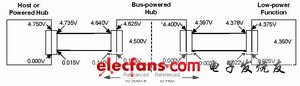
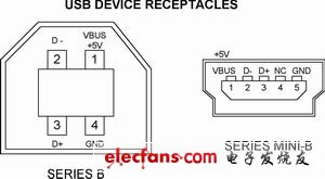
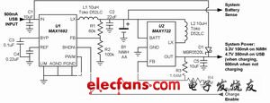
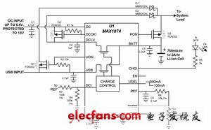
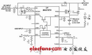
One of the features of the USB standard is to power the inserted USB peripherals from the host. From the past serial and parallel port changes to USB, this advancement has greatly increased the number of devices connected to the PC. In addition to direct powering USB devices, one of the more useful features of USB is to charge the battery with a USB power source. Since many portable devices (such as MP3 players, PDAs) exchange information with the PC, battery charging and data exchange at the same time on one cable will greatly enhance the convenience of the device. Combining USB and battery-powered features expands the range of work for "unrestricted" devices such as mobile web cameras connected to a PC or not connected to a PC. In many cases, it is not necessary to carry an inconvenient AC adapter. Charging the battery from USB can be complicated or simple, depending on the USB device requirements. The factors that have an impact on the design are usually "cost", "size" and "weight". Other important considerations include: 1) how fast the device with the discharged battery can enter full operation when the device is plugged into the USB port; 2) the allowed battery charging time; 3) the USB-limited power budget; 4) Necessity to include AC adapter charging. This article will provide a solution to these problems after detailing USB from a power point of view. Figure 1 USB voltage drop (from Universal Serial Bus Specification Rev2.0) Figure 2 USB device jack Figure 3: Simple charging from USB 100mA and charging from AC adapter 350mA does not require enumeration because the USB charging current does not exceed "one unit load" (100mA). 3.3V system load always draws current from the battery USB power supply All host USB devices (such as PCs and laptops) can supply at least 500mA or 5 "cell loads" per USB port. In the USB statement, "one unit load" is 100 mA. The self-powered USB jack can also provide 5 unit loads. The bus-powered USB jack guarantees a unit load (100mA). According to the USB specification and the description of Figure 1, at the cable peripheral end, the minimum effective voltage from the USB host or power jack is 4.5V, while the minimum voltage from the USB bus power jack is 4.35V. These voltages are very small when charging a Li-Ion battery (typically 4.2V is required). All devices plugged into the USB port must not draw more than 100mA. After communicating with the host, the device can determine if it can occupy the entire 500mA. The USB peripheral contains one of two jacks. Both jacks are smaller than the jacks in PCs and other USB mainframes. The "SeriesB" and smaller "Series Mini-B" jacks are shown in Figure 2. Power is supplied from pins 1 (+5V) and 4 (ground) of SeriesB and pins 1 (+5V) and 5 (ground) of Series Mini-B. Once connected, all USB devices require the host to recognize them. This is called "enumeration." During the identification process, the host determines the power of the USB device and whether it is powered. For approved devices, the load current can be increased from 100 mA to 500 mA. Simple USB/AC adapter charging circuit Some very basic devices do not expect additional software overhead, which is required for the classification and optimal use of an effective USB power source. If the device load current is limited to 100mA (referred to as "one unit load" in USB), any USB host, self-powered jack can power the device. For this design, a very basic charger and regulator circuit is shown in Figure 3. This circuit charges the battery whenever the device is connected to a USB or plugged into an AC adapter. At the same time, the system load is always connected to the battery, in which case up to 200mA can be supplied through a simple linear regulator (U2). If the system continuously draws such a current amount and the battery is charging from USB at 100 mA, the battery will still discharge because the load current exceeds the charging current. In most small systems, the peak load only occurs for a fraction of the total operating time, so only the average load current is less than the charging current and the battery will still charge. When the AC adapter is connected, the maximum current of the charger (U1) is increased to 350mA. If the USB and AC adapters are connected at the same time, the AC adapter automatically assumes the priority power supply status. One feature of U1 is required by the USB specification (also a general charger rule), which never allows current to be fed back from the battery or other power input to the power input. In the general charger, the input diode can be guaranteed, but the difference between the minimum USB voltage (4.35V) and the required lithium-ion battery voltage (4.2V) is small, even with Schottky. Diodes are also not suitable. For this reason, all reverse current paths are disconnected in the U1 IC. The circuit of Figure 3 has some limitations that make it unsuitable for some rechargeable USB devices. The most obvious limitation is its relatively low charging current, which makes it very time consuming to charge a lithium ion battery that is more than a few hundred milliamps an hour. The second limitation is that the load (linear regulator input) is always connected to the battery. In this case, the system is not able to work immediately after insertion because the battery is deeply discharged and there is a delay before the battery reaches a sufficient voltage to operate the system. Load switching and enhanced circuit In more advanced systems, the charger or surrounding charger requires some enhanced performance. This includes selectable charging currents to accommodate different power supplies or battery power supplies, load switching when plugged in, and overvoltage protection. The circuit shown in Figure 4 adds these features, which are implemented by an external MOSFET driven by the charger IC voltage detector. MOSFETs Q1 and Q2 and diodes D1 and D2 bypass the battery and directly connect the active (USB or AC adapter) power input to the load. When the power input is active, the DC input has priority; U1 prevents both inputs from being active at the same time. Diodes D1 and D2 prevent reverse current flow between inputs generated by the "system load" power path, while the charger has built-in circuitry to eliminate reverse current through the charging path (at BATT). The MOSFET also provides AC adapter overvoltage protection (up to 18V). The under/overvoltage monitor allows the AC adapter voltage to be only between 4V and 6.25V. The MOSEFT Q3 turns on when there is no active external power source to connect the battery to the load. When the USB or DC power supply is connected, the PON (power switch) output immediately turns off Q3, disconnecting the battery from the load. The system works immediately when external power is applied, allowing the battery to work immediately even if it is deeply discharged or damaged. When USB is connected, the USB device communicates with the host to determine if the load current can be increased. If the host allows, the load starts at a unit load and increases to 5 unit loads. The current range of 5 to 1 unit load is a problem for a typical charger (not designed for USB). The accuracy of the general charger, although it can meet the high current requirement, is usually not satisfactory in terms of low current setting due to the deviation of the current detecting circuit. The result is that a small range of charging current (1 unit load) must be set low enough to ensure that the 100 mA limit is not exceeded. For example, for a 10% accuracy of 500mA, the output must be set to 450mA to ensure it does not exceed 500mA. This is only acceptable; however, in order to ensure that the low charging current does not exceed 100 mA, its rated current must be set to 50 mA, and the minimum value may be 0 mA, which is clearly unacceptable. If USB charging is effective in both ranges, sufficient accuracy is required so that the maximum possible charging current does not exceed the USB limit. In some designs, system power requirements require less than 500mA USB budget to power the load and charge the battery separately, but using an AC adapter is not a problem. The circuit shown in Figure 5 (the simplified subsystem of Figure 4) is an economical connection method. The USB power supply is not directly connected to the load. Charging and system operation still occurs on the USB power supply, but the system remains connected to the battery. The limit is the same as in Figure 3: When the USB is connected, if the battery is deeply discharged, the system can have a delay before working. If the DC power supply is connected, the operating state of Figure 5 is the same as that of Figure 4, with no waiting time, regardless of the battery status. This is because Q2 is turned off and the D1 system load is transferred from the battery to the DC input. NiMH battery charging circuit Although lithium-ion batteries provide the best performance for most portable devices, NiMH (NiMH) batteries are still a viable option for low-cost designs. When the load requirements are not too strict, a good way to keep costs low is to use NiMH batteries. This requires a DC-DC converter boost, typically rising from a 1.3V battery voltage to the voltage available to the device (typically 3.3V). Since any battery-powered device requires a voltage regulator, the DC-DC converter is just a different regulator. The circuit shown in Figure 6 uniquely charges the NiMH battery and switches the system load between the USB input and the battery without an external FET. The "charger" is actually a DC-DC boost converter (U1) that operates under current limiting. Charge the battery with a current between 300 and 400 mA. Although there is no precise current source, it has proper current control to maintain current control even when the battery is shorted. The biggest advantage of the DC-DC charging topology over the general linear solution is the efficient use of limited USB power resources. When charging with a 400 mA current NiMH battery, the circuit draws only 150 mA from the USB input. The remaining 350 mA is used for the system during charging. Diode D1 pulls the load from the battery to the USB. The boost converter produces a 3.3V output when USB is not connected. When USB is connected, the D1 pull-up DC-DC boost converter (U2) outputs to about 4.7V. When the U2 output is pulled up, it automatically turns off and the current drawn from the battery is less than 1 mA. For USB connection, if the output is not acceptable for conversion from 3.3V to 4.7V, a linear regulator in series with D1 can be added. The limitation of this circuit is that the system is used to control the end of charging. U1 is only used as a current source. If it is left unused for a long time, it will overcharge the battery. R1 and R2 set U1's maximum output voltage to 2V as a safety limit. The “Charge Enable†input acts to cool the system and reduce the USB load current before enumeration because the charger's 150mA input current is greater than one load. ■Figure 4. The SOT-23 power MOSFET adds useful performance (such as overvoltage protection and disconnecting the battery when the power supply is applied). When the battery is charged without load, the active power directly drives the system. Figure 5 The simple design allows the USB power supply to not be directly connected to the load, but instead is DC input to the load. When the USB is connected, the system is still powered by the battery and the battery is charging. Figure 6. A simple NiMH charge/power configuration automatically transfers power to the USB with a complex MOSFET switch array.
Project lamps is based on the actual needs of the project, customized for the specific lighting products, it plays decorative effect, also known as non-standard lamps, decorative lamps, custom lamps and so on. Engineering lamps feature with custom, long production time, high production technology, strong professionallity , weak liquidity, highly difficult installation, after-sales service and so on.
Project Lamp,Rechargeable Spot Light,Lobby Room Project,Airport Project Zhongshan Laidi Lighting Co.,LTD , http://www.idealightgroup.com