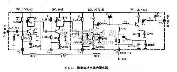
The RF power amplifier can output 2-3 channel signals with a coverage area of ​​about one square kilometer. It is an ideal device for starting a small TV launch pad and is suitable for electrification education. However, it should be reported to the local radio management committee for use and can only be implemented after approval. This article refers to the address: http:// Circuit working principle The working principle of the device circuit is shown in Figure 8.31. A staggered tuned amplifier is formed by transistors BG1, BG2, and BG3. The collector load of the BG3 is a lower-level input matching network that avoids self-excitation and maximizes signal transmission gain. BGl, BG2, and BG3 work in the Class A state. BG4 focuses on improving high-frequency dynamic characteristics, working in Class C, high efficiency, and its base uses a self-supplied negative bias circuit, which is beneficial to improve the temperature stability of the triode. The output of BG4 is a matching network that allows the signal to be efficiently transmitted to the transmitting antenna. The whole machine is powered by a negative power supply. C7-C10 is a feedthrough capacitor for anti-interference of power supply lines. Component selection and production BGl and BG2 use ultra-high frequency and low power triodes with high fT and low noise, such as 3DG30C or 9018. BG3 selects medium power transistor such as 2G711, fT>= 500MH. , IC = 50 mA, PCM = 500 mW. BG4 selects triodes such as 3DA37 or MRF517, and requires fT>=500MHz and PCM>=1w. The coils used in the circuit are all air core coils. Ll, L2 is wrapped around the round pencil rod by 7 times with an enameled wire with a diameter of 0.97mm, and tapped at 3 turns to the ground. L3 and L4 are painted and tinned with a 1.3mm diameter enameled wire, and then wrapped around the color pen holder for 6 times and then pulled to 150mm. L6, L7 with a diameter of 1.3mm enameled wire to paint tinned, then wrapped around the color pen rod 3 times and then pulled to 7mm, L5 with a diameter of 0.77mm enameled wire on the pencil rod close to 8 circles. The RFC coils used were all wrapped around a 1/2 w, 1.5 k resistor with a 0.41 mm diameter enameled wire. The printed board of this machine adopts double-sided epoxy copper-clad board, and the components are welded on one side; the other side is connected with the ground for shielding. When soldering, the component leads are short, making full use of the strength and resistance of the solder tabs at both ends of the variable capacitor. The non-grounding end of the capacitor serves as a supporting point to connect the components in a floating manner, and the variable capacitor rotor is grounded. All triodes use a basket-type connection to prevent high frequency self-excitation. After all the components are soldered, the isolation board and the shielding box are installed, and then the core-through capacitor is mounted on the side of the shielding box, and the high-frequency choke coil is welded. When debugging, first adjust the DC operating point of the triode. Disconnect the coupling capacitors between the stages, and adjust the resistance of R1, R2, and R3 on the voltmeters of the DG1 to BG3, respectively, so that the voltmeter indicates: BG1: e is extremely 15V, BG2:e Extremely 1.0V, BG3:e is 1.3V. Then connect the coupling capacitor and load, turn on the power, if there is self-excitation, fine-tune the trimmer capacitor to eliminate. Then connect the 2 or 3 channel RF signal output from the recorder to the input end of the amplifier, and fine-tune the capacitor while observing the image on the TV screen. First disconnect the third level. Connect the 75 ohm antenna to the second-stage output, adjust C1, C2 to make the TV's image and sound better, then connect the third and fourth stages, and connect the antenna to the output. Reduce the power supply voltage, adjust C3, C4, make the BG4 collector current maximum, adjust C5, C6, and make the BG4 collector current minimum. Finally, put the TV set to a distant place, fine-tune C1 ~ C6, so that the image is clear, the sound is loud and pleasant, and the color is the most beautiful. This amplifier is only suitable for video recorders with 2 to 3 channels of RF output. For recording and playback cameras with other channels, the video and audio signals must be modulated on the 3 channels and sent to the amplifier.    HDMI Adapter Cable,A Hdmi Antenna,Phone HDMI Cable Phone to TV,HDMI Cable Dongguan City Leya Electronic Technology Co. Ltd , https://www.dgleya.com