12V Power Adapter,Catv Linear Power Adapter,Linear Mode Power Adapter,Catv Linear Mode Power Adapter Ninghai Yingjiao Electrical Co., Ltd. , https://www.yingjiaoadapter.com
Keywords: Bluetooth local network gateway physical link logical link
1 Introduction to Bluetooth PSTN Telephone Gateway
1.1 Introduction to Bluetooth technology The goal of Bluetooth technology is to provide a common wireless interface standard, to replace the intricate cables in traditional networks with wireless channels, to achieve convenient, fast, flexible, safe, low-cost and low-power consumption among Bluetooth devices Data and voice communication. The Bluetooth device works in the 2.4 GHz ISM (Industrial, Science and Medicine) band. In the 1.0 version of the standard, Bluetooth's baseband symbol rate is 1Mbps. Bluetooth supports real-time voice transmission at 64kb / s and data transmission at various rates. Voice coding uses logarithmic PCM or continuous variable slope delta modulation (ConTInuousVariable Slope Delta ModulaTIon, CVSD). Voice and data can be transmitted separately or simultaneously. When only transmitting voice, Bluetooth devices can support up to 3 full-duplex voice communications at the same time.
1.2 Introduction to Bluetooth Telephone Gateway Among various applications of Bluetooth, the "three-in-one phone" is undoubtedly an exciting one. Users with "three-in-one phone" can do: only pay a fixed telephone fee for indoor use, just like an ordinary mobile phone outdoors, in the office and other occasions, you can use the company's internal telephone network without Paid. But the "three-in-one phone" can't achieve the above-mentioned functions only by its own Bluetooth function. It also needs the support of the Bluetooth phone gateway. As shown in Figure 1, the Bluetooth PSTN (Public Switched Telephone Network) telephone gateway provides a new short-distance access method for terminals with Bluetooth telephone functions to connect to the fixed telephone network. The terminal with Bluetooth phone function can be a simple cordless phone or a cordless modem in a personal computer. 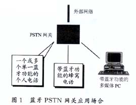
Functionally speaking, the Bluetooth PSTN gateway is mainly an interface between Bluetooth TCS (Telephony Control SpecificaTIon) signaling and PSTN signaling. It is responsible for converting the received TCS signaling sent by the Bluetooth cordless terminal into DTMF (Dual Tone MulTI-Frequency) signaling recognized by the PSTN network, and of course including the transmission of voice. Specifically, it can transfer calls from external PSTN network users to Bluetooth cordless terminals within the effective range, and can also send call requests from Bluetooth cordless terminals within the effective range to PSTN network users to the PSTN network.
2 Overall design scheme of Bluetooth PSTN telephone gateway
2.1 The software on the Bluetooth PSTN telephone gateway is an application specified in the Bluetooth protocol. The software stack in the Bluetooth PSTN telephone gateway system must meet the requirements of the Bluetooth protocol, that is, the application model of the Bluetooth PSTN telephone gateway. .
The application model is a solution provided by the Bluetooth protocol for various applications. It consists of a vertical segmentation of the Bluetooth protocol stack and is the basis for the interoperability of various applications that comply with the Bluetooth specification. Each application model must complete its function through a combination of corresponding protocol layers, and each Bluetooth device supports one or more application models. Bluetooth SIG defines four general application models as the basis for other specific application models: general access model, serial port model, service discovery model and general object exchange model. A specific application is usually limited by several models related to it.
According to the Bluetooth protocol, the application model of the Bluetooth PSTN gateway is based on the universal access model and service discovery model. The application model defines the requirements and processes for the cooperative work between the parts of the "three-in-one phone". The application model includes the following layers: Bluetooth baseband, link management protocol, L2CAP, service discovery protocol, telephone control signaling, and general access model.
2.2 Hardware on the Bluetooth PSTN telephone gateway The hardware on the PSTN telephone gateway is mainly composed of a PC, an Ericsson EBSK (Ericsson Bluetooth Starter Kit) and telephone voice receiving and dialing circuits, as shown in Figure 2. The following briefly introduces the functions of these three parts. 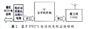
The Bluetooth EBSK module includes a Bluetooth radio frequency circuit and a baseband processing circuit. The module provides RS232 serial port and PCM (Pulse-Amplitude Modulation) code stream port. Various control signals and data signals are transmitted through the serial port. The voice signal is transmitted through the dedicated PCM code stream port. The PC interprets the data received by the Bluetooth module using the radio frequency circuit and the baseband processing circuit through the protocol stack as off-hook, on-hook, dialing and other commands and controls various operations of the telephone voice receiving and dialing circuit through the data line. The PSTN local telephone network subscriber line is connected to the telephone voice receiving and dialing circuit. The telephone voice receiving and dialing circuit transmits the ringing signal of the external PSTN telephone network to the PC through the data line. The PC then sends the signal into a data packet through the Bluetooth software stack and sends it to the Bluetooth module, which is transmitted by the Bluetooth module . The voice channel is connected to the PCM voice encoder through the level conversion of the earphone and microphone interface of the telephone voice receiving and dialing circuit. The resulting PCM code stream is directly sent to the Bluetooth module and transmitted to the voice terminal. Similarly, the required PCM code stream is also directly provided by the Bluetooth EBSK module.
3 Software protocol system We can see from Figure 3 that the Bluetooth gateway software system includes several levels. They are TCS, SDP (Service Discovery Pr otocol), ME (Management Entity), L2CAP (Logical Link Control and Adaptation Protocol), HCI (HostControlInterface) and application layer. Each of these levels will be introduced below. 
3.1 Application layer
3.1.1 Structure definition The application model defines the following two devices: gateway (GW) and terminal (TL). From the perspective of the external telephone network, the gateway is a terminal that handles various interoperations with the external network, such as sending call requests to the external network or receiving call requests from the external network. The gateway can be PSTN home gateway, ISDN home gateway, GSM gateway, satellite gateway and H. 323 gateway. The terminal refers to a wireless user terminal. It can be a cordless phone, cellular / cordless dual-mode phone or PC. The cordless telephone application model supports the topology of a gateway and a small number of terminals (≤7).
3.1.2 User requirements The application model should meet the following requirements: use TL to make calls to external network users; answer calls from external network users; direct calls between two internal TLs; use auxiliary services provided by external networks
3.1.3 Basic principles of application model In the application model of cordless telephone, the gateway is usually the host of the piconet. As a host, the gateway will control the power mode of the terminal and broadcast information to the terminal.
Terminals outside the effective range of the gateway search the gateway through periodic call information. The gateway must scan as many calls as possible to find remote terminals that are within range as soon as possible. This scheme reduces electromagnetic pollution and provides reasonable access time when entering the effective range of the gateway. When the terminal successfully calls the gateway, the master-slave switching operation must be performed because the gateway must be the host. At this point, a connection-oriented L2CAP channel or connection-free L2CAP channel has been established and is used to transmit all TCS signaling during a cordless telephone conversation.
Terminals that are within the effective range of the gateway but not currently used must be in sleep mode. In this mode, the power is turned on, it can provide a reasonable call set-up time when needed, and allows broadcasting information to the attached terminal (if it exists).
When a call comes in or the terminal wants to make an outgoing call, the gateway must be activated. All TCS control signaling is transmitted by the L2CAP channel, and voice is transmitted by the SCO (Synchronous Connection-Oriented) link.
For security, the gateway and terminal must be authenticated. In order to facilitate the reliable transmission of information between wireless devices, the concept of WUG (Wirel ess User Group) is used. The gateway is usually used as a WUG host.
The application layer should manage connections at three levels, namely: physical link connection, logical link connection, and application connection. The agreement stipulates that one of the security mode 3 or security mode 2 must be complied with in the PSTN gateway application. Security mode 3 is a security mechanism established on the physical link, and security mode 2 is a security mechanism established on the logical link. Before establishing a logical link, the voice terminal must use SDP to perform service discovery on surrounding Bluetooth devices in order to find the PSTN telephone gateway. After the logical link is established, the gateway will use the TCS layer on the logical link to perform a series of information interactions with the voice terminal in order to establish a connection at the application layer.
3.2 Physical link establishment process We chose security mode 3 when designing the PSTN telephone gateway, which means that the authentication process was performed when establishing the physical link. This requires the telephone gateway and the voice terminal to pair in the baseband when the connection is first established, and requires the voice terminal to comply with the PIN code required by the telephone gateway.
The gateway supporting multiple terminals must always be the host of the piconet. Such a gateway should issue a master-slave switch request when a terminal is connected. If the terminal rejects the request, the gateway will not establish a connection with it. Therefore, the terminal that does not accept the master-slave handover request cannot obtain any gateway service.
The gateway should be very conservative when deciding which power mode to put each terminal in. That is, when a terminal does not transmit a signal, the gateway should put it in power saving mode. The recommended power saving mode is the sleep mode. However, the appropriate power saving mode parameters must be selected during sleep, so that the terminal can be returned to the working state within 300ms.
When the gateway does not support the sleep mode, it is up to the terminal to decide how to handle the link when there is no call: maintain the working state or release the link. After the link is released, both the master and slave should be able to rebuild the link when needed. In this case, when there is no valid link, both the master and slave should be in the call scanning state.
If the gateway can save power during the call, it can use the monitoring state. The terminal can also be asked to enter the monitoring state.
3.3 Service discovery process After the physical link is established, the SDP process begins. The following briefly introduces this process.
The service discovery protocol works on L2CAP, using the connection-based working method provided by L2CAP. It can be divided into two parts, as shown in Figure 4. The client part of the service discovery protocol and the server part of the service discovery protocol in the figure work on different Bluetooth devices. The Bluetooth device that needs to request service runs the client part of the service discovery protocol, and the Bluetooth device that provides the service runs the server part of the service discovery protocol. A Bluetooth device may contain both the server part and the client part depending on its situation. On the client, the client application issues a service discovery request. On the server side, the server-side application registers its service attributes with the server. The service discovery protocol searches for services according to the type of service, that is, one Bluetooth device A tells another Bluetooth device B the type of service it wants to find, so that device B returns the service record that meets the requirements to device A. Next, device A finds useful information in the returned service record. In the application of the Bluetooth PSTN telephone gateway, the gateway serves as the upper-layer application of the server side in SDP, and needs to register the service attributes specified in the protocol to the SDP server during initialization. The terminal can discover the service provided by the gateway through the SDP process before establishing the logical link and establish a logical link with it. 
3.4 Logical link establishment process Before the terminal establishes a connection at the application level with the gateway through TCS, it should first configure the link and establish and configure the L2CAP connection for signal transmission during the TCS-BIN process. Only terminals that pass authentication can connect to the gateway. In order to avoid excessive delay in call establishment and receiving broadcast information, when the terminal enters the valid interval of the gateway, it establishes a logical link channel with the gateway and maintains it until the link is lost or the terminal is shut down. The logical link connection will be idle for a long time after being used.
This application model uses connection-oriented channels and connection-free channels. The gateway broadcasts information to each voice terminal using a connection-free channel. Only Fengguan can use connectionless channels to send messages. The use of logical link connectionless channels must meet the requirements of the Bluetooth Security Architecture White Paper. In this application model, only voice terminals can initiate the establishment of connection-oriented channels. When connecting with the gateway, the terminal must use the value 0x0007 (TCS-BIN-CORDLESS) in the PSM field of the connection request packet. Below we give a brief introduction to TCS.
3.5 Telephone Control Signaling (TCS) and its analysis The Bluetooth TCS (Telephony Control Specification) protocol defines the call control signaling required for establishing voice and data calls between Bluetooth devices, and for managing Bluetooth devices with voice functions Control process.
TCS protocol is based on ITU-TQ. 931 suggests that the part of peer-to-peer calls is adopted, that is, in the Bluetooth TCS device, only the calling party (originating the call) and the incoming party (ending the call) are distinguished. The TCS protocol is divided into three functional blocks (as shown in Figure 5). In Figure 5, CC-Call Control, call control; GM-Group Management, group management; CL-Connectionless TCS, connectionless TCS. Among them, call control is used to establish and release control signaling for voice or data calls; group management refers to the control process of managing a group of TCS devices; connectionless TCS is used to exchange signaling information, which is not related to the current ongoing call . 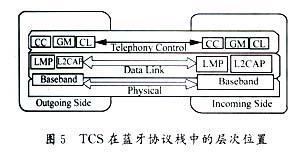
There are two basic operations for TCS equipment, one is point-to-point call control, and the other is point-to-multipoint call control. The former is used when the called party is known and uses the connection-oriented L2CAP channel; the latter is used when the called party cannot be clearly determined, such as when an external call comes in, the switch needs to notify all TCS within the effective range Equipment to further determine the called party. Point-to-multipoint control signaling can only use connection-free L2CAP channels.
The TCS device supports multiple calls at the same time, and each call instance can be distinguished by the ID number of the L2CAP channel carried.
4 Test results and improvement schemes We have used the above gateways and mobile phones to realize the communication between mobile phones and external PSTN users. Including mutual calls, answering and handling when no one answers. According to the actual measurement, when the distance between the mobile phone and the gateway is within six meters, the call quality is quite good, and the voice is clear and without distortion. When the distance is greater than six meters, the voice will jitter. This is because the bit error rate of transmission increases when the distance increases, resulting in intermittent speech, and subjective auditory perception of jitter. This is because the Bluetooth module used only supports 1 milliwatt of transmit power, which can be improved if a higher-power Bluetooth module is used.
In addition, the side tone of the gateway is large, because the resistance of the output resistance of the side tone amplifier has not been adjusted to the best. Further adjustment of the resistance is expected to reduce the side tone. The gateway is severely affected by external electromagnetic interference. This is because the printed circuit wiring of the voice input part is not very reasonable, and this phenomenon can be improved by improving the wiring in the next version.
2 http: //. com. BSIG, Specification of the Bluetooth System (Profile), Versi on 1.0B. 1999, 12
Implementation of Bluetooth PSTN telephone gateway on PC
ã€Abstract】 This paper introduces the overall structure of the Bluetooth telephone gateway realized by peripheral circuits on a PC, introduces its software and hardware structure in more detail, and proposes improvements to the shortcomings of the program.
references
1 http: //. com. BSIG, Specification of the Bluetooth System (Core), Version 1.0B. 1999, 12