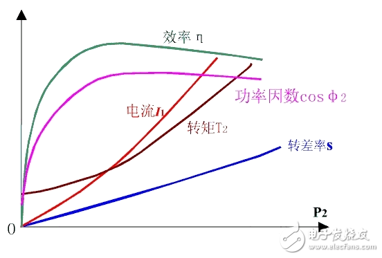
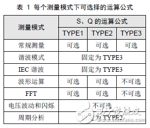
Power factor, which is the ratio of active power to apparent power, is one of the main performance indicators of asynchronous motors. From the perspective of equivalent circuits, asynchronous motors are an inductive circuit that must absorb inductive reactive power from the grid, and its power factor is always less than one. When the motor is no-load, the rotor current is approximately equal to zero. The stator current is basically the excitation current. The main component is the magnetizing current. Therefore, the power factor at no-load is very low, about 0.2. After the motor is loaded, the rotor current increases, the mechanical power of the output increases, and the active component of the stator current increases, so the power factor of the stator increases rapidly. However, when the load increases to a certain extent, the load increase causes the slip ratio s to be large, the phase angle between the voltage and current of the rotor is large, the power factor of the rotor decreases, and the power factor of the stator also decreases. In other words, within the normal working range, only the maximum power factor is available at a certain load, usually the maximum power factor is around the rated load or slightly below the rated load, generally 0.7~0.9, while no load, light load The power factor is very low. For the accurate measurement of the motor power factor, it is generally necessary to improve the accuracy of the measurement from the following aspects. 1. Whether the electrical parameters are measured accurately is the basis for the accurate measurement of most of the parameters of the motor, including the power factor, and what is the standard for accurate measurement of electrical parameters? In fact, it is very simple, the waveform of each electrical parameter is stable and free of clutter. 1) First of all, you must ensure that the range is appropriate. For measurement, this is the most important point. Choosing the right measurement range is equivalent to selecting tools with different precisions. Imagine if you can measure the diameter of a refill with a meter ruler. How can this be measured? If you measure directly, if you find that the current measurement is less than 30% of the maximum range, then you need to adjust the current measurement range. If you measure indirectly through the current sensor, the current measured value is less than 30%* range, or the displayed value is less than 30%*range* sensor ratio, then you need to adjust the current measurement range. Of course, you have to make sure that your measurement process is not over-range. 2) Is there a deviation in the range adjustment? Then you may need to set up the appropriate line filtering. The cutoff frequency of the line filter needs to be considered according to the waveform of the electrical parameter. The purpose is to filter out the clutter, and the final result is to make the waveform "clean" without clutter. Of course, if the cutoff frequency is too high, the clutter may not be filtered. If the cutoff frequency is too low, when the motor speed increases, and the PWM wave frequency from the inverter rises above the cutoff frequency, the PWM wave that needs to be measured passes. A layer of filtering produces distortion, making the measurement inaccurate. 3) Normally, our system has a default update rate, so the default can accurately test the electrical parameters above a certain frequency. If the measured motor speed is lower, that is, the frequency of the motor input electrical parameters is lower, the system defaults. The update rate does not meet the test conditions. At this time, the update rate of the power analyzer must be changed to suit the test requirements. After the first point is completed, the next step is to select the appropriate reactive power calculation formula. The MPT1000 motor test platform provides three practical formulas for reactive power calculation for different test modes. In different test modes, if there is a deviation in the reactive test, if the reactive power calculation formula is selected in the test mode, the calculation formula closest to the true value can be selected according to its own needs. If the user test signal line is too long, the measurement error generated by the line can not be ignored. In this case, line compensation needs to be added to compensate the measurement error generated by the line, so that the calculated value is closer to the true value we need, and the more accurate the compensation setting is, The more accurate the measurement is. In addition, during the use of the equipment, due to changes in environmental conditions, temperature changes or other factors, there will be a certain drift in the zero point of the measuring instrument. At this time, the zeroing operation should be performed to prevent zero drift error. Power factor is one of the important properties of asynchronous motors, and the accurate measurement of motor power factor is mainly considered by the following points: 1. Ensure the measurement conditions of electrical parameters: range, anti-interference, update rate, etc. 2. Select the appropriate reactive power calculation formula. 3. Properly zero and compensate. Gaming And PC Headphones,PC Headphones,Cheap Wired Headphones,Best Wired Gaming Headphones TOPWAY EM ENTERPRISE LIMITED , https://www.topwayemltd.com