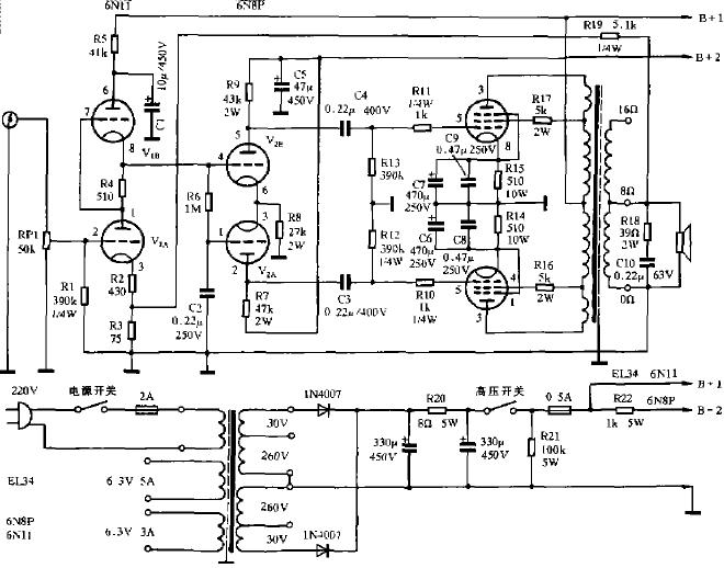
First, the circuit design This article refers to the address: http:// The EL34 amplifier circuit is shown in Figure 1. The first stage voltage amplification uses SRPP single-ended push-pull circuit, the second stage uses long tail type inverter and push circuit, and the last stage adopts super linear connection push-pull output circuit. The three-stage amplifying circuit is a cathode self-supplied gate bias. The EL34 amplifier is selected as the Class A working state and the amplification characteristic. The characteristics of the circuit are determined by the internal and external conditions of the tube. Therefore, the screen pressure and the screen flow on the tubes at all levels are required to conform to the characteristic curve of the electron tube and the peripheral circuit. (1) SRPP voltage amplifying circuit The first stage of Figure 1 uses an SRPP circuit consisting of 6N11. The DC paths of the upper and lower tubes of V1a and V1b are connected in series. V1a constitutes a three-stage common cathode voltage amplifying circuit, and the gate bias is self-contained, which is generated by the cathode current of R2 and R3. Without the cathode capacitor, the gate bias will fluctuate with the amplification, so there is current negative feedback at this stage. V1b constitutes a cathode output circuit and acts as a constant current load for V1a. The constant current value is biased by the negative resistance of R4. The input signal is provided by the screen of V1a and then by the cathode of V1b. Since the cathode follower has a voltage amplification close to one. Therefore, the SLPP voltage amplification depends on V1a. R2+R3 and R4 are required to use the same resistance. The center of the first stage filament winding must be grounded in order to prevent the filament voltage from causing hum. The upper and lower tubes of the SRPP circuit are powered in series. The upper tube cathode has half the supply voltage. There is a potential difference of about 100V between the cathode and the filament, which is too high, which will cause a breakdown short circuit between the cathode and the filament. Therefore, when using SRPP as the first-stage amplification circuit, attention must be paid to the withstand voltage between the cathode of the tube and the filament. The SRPP circuit is quite excellent, its frequency bandwidth and distortion are low, especially the high-frequency characteristics are more prominent. As the pre-stage voltage amplification, its sound characteristics are high resolution, and the sound bottom is refreshing and smooth. (2) Inversion and promotion The second stage uses a 6N8P long tail inversion and push circuit. The upper and lower tubes are cathode coupled. The upper tube is a common cathode circuit. The signal is input from the gate; the lower gate is grounded through a 0.22uF capacitor, which is a common-gate circuit, and the signal is input from the cathode. The upper tube has a common cathode circuit, and the gate and screen signals are inverted by 180 degrees, and the gate and cathode signals are in phase. The lower common circuit circuit, the negative and the screen signals are in phase. Therefore, the screen of the upper tube and the screen of the lower tube are inverted by 180 degrees. When the voltages of the upper and lower screens are equal, the signal voltage outputted by the upper and lower tubes is an amplified signal with opposite phases and equal output amplitudes. The phase inversion and push circuit output voltage amplitude Upp from 60V to 130V can meet the driving voltage requirements of the final stage power amplifier tube. The upper tube of this stage is a common cathode circuit, and the lower tube is a common gate circuit. The common gate circuit has a lower gain than the common cathode circuit. In order to increase the amplification amount of the common gate circuit, it is necessary to appropriately increase the screen load resistance value of the common gate circuit. The first and second stages of the machine adopt direct coupling, and the second and third stages adopt RC coupling. The second stage cathode resistor R8 and the output coupling capacitor 0.22uF are coupling elements of the long tail inverter circuit. Since the output of the upper tube drives the output of the lower tube, there is a certain time constant and delay, which sounds better. The 1MΩ resistor is the gate leakage resistance of the lower tube, and the voltage across the 1MΩ resistor is used as the lower tube gate bias. And the gate bias of the upper tube. It is generated by a cathode current from a cathode resistance of 27 kΩ. (3) Super linear push-pull power amplifier stage The final stage is connected to a super linear push-pull power amplifier circuit by two pentodes EL34. After finding a pair of optimal taps SG1 and SG2 at the primary of the output transformer, it is connected to the curtain grid of the power tube EL34 through the SG1. The SG2 taps the feedback of a portion of the EL34's screen output voltage to the screen grid. It has both the output power of the pentode and the low distortion of the triode to achieve so-called superlinearity. The output transformer of the machine itself has a primary inductance Lp>50H and a DC current of 120mA. The measured results show that the frequency response is very flat in the frequency range of 80 Hz to 15 kHz, and the unevenness is ≤ 2 dB. 20Hz ~ 20kHz unevenness ≤ 3dB. R10, R11 1KΩ on the upper and lower tubes are resistors to prevent high-frequency parasitic oscillation; R12, R13 390kΩ are gate leakage resistance, R14, R15 510Ω2W are the cathode resistance of EL34 two tubes, which are generated at the ends of R14 and R15 through the cathode current. The voltage drop is used as the gate bias of the two tubes. The machine is designed according to the Class A power amplifier. The working point of the EL34 power amplifier tube is selected at the midpoint of the dynamic characteristic curve. When the sine wave signal is input, the signal voltage has a screen flow during the entire period of the gate change, and the screen is turned on. The angle is equal to 360 degrees. Therefore, the distortion is minimal and the signal details are excellent. (four) power supply The power supply consists of a power transformer screen high voltage, a gate negative bias, and a filament voltage. The machine power transformer uses 250W, C-type iron core. Primary 0-240V-220V two groups; secondary 260V+30V two groups, after full-wave rectification by 1N4007 power rectifier diode, can provide B+ DC high voltage 380V, EL34 filament voltage 6.3V, 5A two groups, 6N11, 6N8 filament voltage 6.3 A group of V 3A. For transistor rectification and tube power amplifier circuits, the high and low voltage power switches of this unit are separately set. When starting up, first open the low-voltage filament power switch, preheat the tube filament for 3 to 5 minutes. Turn on the high voltage power switch again. When shutting down. Then turn off the high voltage switch first, and turn off the low voltage switch until the music can't be heard. This helps the electrolytic capacitor discharge and delay the life of the tube. Some people think that high and low voltage use a switch, open and shut down at the same time. I can't agree. The power supply circuit is shown in Figure 1. Convection Heater Convection Heater Convection Heater, Natural Convection Heater, Waterproof Convection Heater, Panel Convection Heater Ningbo APG Machine(appliance)Co.,Ltd , http://www.apgelectrical.com
For the manufacture of electronic tube machine, it is necessary to consider the four steps of structural design, component assembly, overall layout and installation steps. Briefly read as follows:
(1) Structural design
The metal chassis is a bracket for all components of the whole machine, and the RC components are soldered directly to the pins as much as possible. If it is difficult, it can be fixed by 8mm wide bakelite strip. The whole machine adopts full symmetry layout and shortest path design: 220V AC input, fuse, signal input, speaker wiring installation back; high and low voltage switch, volume potentiometer installation front. In order to reduce electromagnetic interference, the power transformer and the output transformer are designed with a shield.
(two) component assembly
The power transformer adopts 250VA, double 260V+ double 30V power transformer with large capacity and low internal resistance; the output transformer requires large primary inductance, small leakage inductance, small distributed capacitance, low phase shift, 40W push-pull output transformer The potentiometer uses a small dynamic noise, logarithmic 100K double-tuning potentiometer, which can improve reliability in parallel; high-capacity electrolytic capacitors for high-voltage rectification and filtering and power supply voltage decoupling require electrolytic capacitors with high withstand voltage and low leakage. ; small-capacity capacitors for coupling between circuit stages, polypropylene CBB capacitors with small dielectric loss and good insulation; resistors with high precision, low thermal noise, metal film resistors, RJ type, screen load resistance, cathode The coupling resistor uses 2W or more resistors; the gate leakage, anti-vibration, negative bias, and negative feedback resistors are small, 0.25W RJ resistors.
(three) machine layout
1. The positions of the amplifiers at each level are preferably arranged in a straight line according to the connection sequence on the schematic diagram, so that the leads between the stages are the shortest, and the "ground" currents at all levels are flowing within the range of this level. It does not flow into other stages of the circuit, resulting in self-oscillation and the like.
2. The power supply line and the audio signal transmission line should be separated as much as possible; the low-level input amplification circuit should be kept away from the high-level output circuit as much as possible; the components that are prone to failure should be installed in an easily replaceable position.
3. The large loop negative feedback resistor and capacitor should be installed at the output end of the output transformer.
4. The wiring of the filament is double-stranded, and the two wires are twisted together. When passing currents in opposite directions, the radiated electric fields will cancel each other out.
5. Turn the volume potentiometer to the signal input jack and the center of the volume potentiometer to the lead between the gates of the first stage. Use shielded wires and shorten the leads as much as possible.
6. How to properly arrange the ground wire and deal with the ground branch problem is also the main method to eliminate the circuit hum and self-excitation interference. This machine adopts a three-level tandem grounding busbar. See Figure 2: 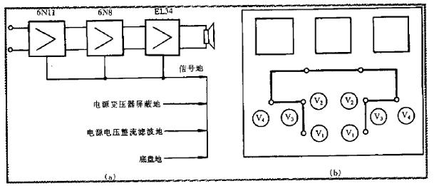
(2) According to the signal transmission direction, the input stage, the phase-inducing stage and the grounding point of the final stage power amplifier are connected in series, and the signal ground of the three stages is insulated from the chassis.
(3) "One-point grounding" is set at the grounding point of the final stage power amplifier. It includes signal ground, shielding ground, power rectification, filtering ground, and chassis ground. The connection to the "one-point grounding" filament needs to be tested. At the pre-stage grounding point.
(four) installation steps
Fix the power transformer, power rectification, and filter RC components on the chassis. Connect them according to the power supply voltage supply diagram. Check whether the power supply is normal and whether the high and low voltages of each group are correct.
Arrange the grounding busbar, filament wire, power supply voltage high and low voltage switch wiring, and install the output transformer, the five-pole power tube EL34, and the inverting push double-pole transistor 6N8P. Voltage amplification double triode 6N11, various levels of RC components. It is required to go from the latter stage to the first level and install it at the first level.
After checking it is correct. Finally, the input stage is shorted, and the output is terminated with 8Ω15W or 16Ω 16W dummy load. Power on all levels of DC voltage, use an oscilloscope to observe whether the machine is self-excited. If there is self-excitation, it means that the lead wires of the primary transformers P1 and P2 of the output transformer are connected incorrectly and the phase is reversed. P1 and P2 can be adjusted at both ends to change the phase of the loop to eliminate self-excitation.
Third, circuit debugging
After the welded amplifier is energized. First, you should measure the working point of each tube to see if it works at its best. Otherwise, adjust the tube working point.
Adjust the working point, according to the data provided in the "Electronic Tube" manual, as the basis for the debugging of the electronic tube machine circuit. The characteristics of the EL34, 6N8P, and 6N11 tubes selected for this unit are shown in Table 1.
(1) Debugging of the first stage SRPP circuit
When the 6N11 double triode is used as the voltage amplifying circuit, the working current should be between 30% and 60% of the maximum screen current of the 6N11 tube, that is, 0.48mA-1.2mA. The upper tube screen voltage should be half of the power supply voltage Ecc=B+. For the SRPP circuit, each tube is divided into half the voltage, and the lower tube screen voltage should be 25% of the power supply voltage. The debugging method for the working point is:
1. By measuring the screen voltage of the lower tube V1a. See if it is one-half of the screen voltage of the upper tube V1b. Measure the screen voltage of the upper tube V1b to see if it is one-half of the power supply voltage B+. Just adjust the resistance of the screen load resistor R5 of the upper tube V1b. When the resistance of the screen resistor R5 is relatively high, the distortion is small. However, at this time, the rectified output must have a higher voltage.
2. By measuring the voltage on the cathode resistance (R2+R3) of the lower tube V1a, it can be converted into the screen current Ia. As long as the resistance of the upper and lower cathode resistances (R2+R3) and R4 are adjusted at the same time, the screen current of the 6N11 lower tube V1a can be adjusted.
In order to get the lowest distortion and large dynamic range. It is required that the two triodes of 6N11 have symmetric performance, and the cathode resistance of 6N11 two triodes is equal, that is, R2+R3=R4.
The first level of SRPP circuit playback is really good, but it has two shortcomings: First, the first and second stage use direct coupling, the first and second working points should be adjusted together; the second is when the input signal voltage is too high The second-stage inverter pushes the circuit to have a gate current, so the input signal voltage is not required to be large.
(2) Debugging of the second-stage inverter driving circuit
The adjustment of the inversion push stage is very important. The output signals of the upper and lower tubes are symmetrical, which is related to the maximum output power and distortion of the whole machine. Because of the different circuit states, the tube screen load resistor R7 should be 10% larger than the upper screen load resistor R9. The two-tube cathode coupling resistor R8 is 10-20kΩ, and the two-tube screen load resistors R7 and R9 are 20-50kΩ. The adjustment method is very simple:
1. By adjusting the resistance values ​​of the upper and lower screens of the screen, the voltages of the upper and lower screens are equal. The screen load resistance of the upper and lower tubes of the machine is 43kΩ and 47kΩ respectively. The screen pressure of both tubes is 190V, and the upper and lower output signals of the inverter output stage are symmetrically equal.
2. By adjusting the resistance of the two tubes of the cathode coupling resistor, the screen current of each tube is about 4.3 mA, so that the output voltage of the two tubes can be balanced. Or the first-stage input terminal sends a 1kHz 200mV sinusoidal signal. When the volume potentiometer puts the maximum volume, the phase-stage cathode coupling resistance is turned down, and the 6N8P upper and lower tube pressure waveforms are observed with an oscilloscope. See if the amplitude is symmetrical. There is no distortion. When the cathode coupling resistance of the machine is R8=27kΩ, the screen current of each tube is 3mA.
(III) Debugging of the final super linear push-pull circuit
The purpose of the push-pull amplifier circuit adjustment is to balance the two push-pull power amplifier tubes of the EL34. The gate bias voltage and the screen current of the two power amplifier tubes are equal.
If the two tube gate biases are not equal, the size of the gate resistors R12 and R13 can be adjusted; if the screen current is different, the resistance values ​​of the two cathode resistors R14 and R15 can be adjusted. The size of the screen stream should be appropriate. Small screen flow is beneficial to the life of the tube.
Pay attention to the adjustment, do not exceed the maximum screen consumption of the EL34 power amplifier tube Pamax = 13.5W. Class A work status. The screen pressure Ua screen Ia of the power amplifier tube is equal to its static screen consumption. When the screen is over, the screen will turn red. After a long time, the power amplifier tube will be burned out.
When adjusting the screen current, you should also pay attention to the change of B+ voltage. If the screen current is large, the B+ voltage will decrease a lot, indicating that the power supply part has insufficient margin or the internal resistance of the power supply is large. If the screen flow difference between the two tubes is large, it means that the power amplifier tubes are not paired, and one power amplifier tube should be replaced. The working point adjustment method of the push-pull amplifier circuit is to adjust the resistance values ​​of the two cathode resistances R14 and R15. The resistance of R14 and R15 is determined according to the sum of the gate bias voltage, screen current and curtain grid current of the EL34 power amplifier tube.
By changing the position of the super-linear connection, it is possible to obtain different amounts of negative feedback of the curtain. By audition, the position of the superlinear optimal taps SG1, SG2 is determined. The EL34 screen of this unit is adjusted to 33mA, its screen pressure is 240V, the output transformer primary SG1, SG2 tap is on the 6-7 terminal, it sounds very good.
(4) Adjustment of negative feedback of large loop
Between the cathode voltage dividing resistor of the first stage SRPP circuit and the output end of the final stage output transformer, R17=5.1K 0.25W is added, which is a large loop negative feedback resistor. Because the electron tube amplifier circuit feeds back the voltage, the negative feedback amount should not be too large, generally about 6dB, and the negative feedback amount of the machine is adjusted to 4.7dB. After the whole machine has large loop negative feedback, it will reduce harmonic distortion, widen the frequency response, and have a good sense of hearing. The adjustment method is mainly to change the resistance value of the negative feedback resistor R17. The amount of feedback is determined according to the sound effects such as sound field, positioning, sweetness of the human voice, and musical sense.
If the negative feedback circuit is just turned on, it will beep. This is the polarity of the negative feedback. If the negative feedback connection is connected to the other end of the output transformer, the terminal can be grounded. Some negative feedback loops are connected in parallel with a small capacitor. If the capacitor is not properly selected, it may cause distortion or self-excitation. Therefore, when this phenomenon is found, simply remove the small capacitor.
(5) Machine testing
After the amplifier circuits of all levels are debugged, the output terminal is connected with 8Ω dummy load, the input terminal inputs 1kHz, 200mV sine wave signal, adjusts the volume potentiometer volume, and uses SR8 oscilloscope at each level of the screen to observe the output signal as the maximum undistorted output voltage waveform. Under the conditions, measure the voltage amplification of each level. Test results of voltage, current and voltage amplification of various tubes. 
The heater on the shell for the outlet, the bottom of the air intake, power after the electric tube around the air is heated to rise from the outlet outflow, and the surrounding cold air from the inlet into the supplement. So repeated cycle, so that the indoor temperature can be improved. When the inlet and outlet are blocked or the ambient temperature is too high, the temperature control element will automatically cut off the electric tube power supply. This heater is used in the power of about 800 watts, but also by increasing the number of electric tube connected to adjust the power. The safety of the heater is high, running quiet, the disadvantage is to slow down the temperature.
EL34 amplifier principle and its making method
Â
Second, production
Â
Â
(1) All the grounding elements of the screen and cathode of the stage and the gate and cathode circuits may be soldered to a grounding point.
Â