Heart rate is a very important life information in the human body, and traditional pulse diagnosis, because of its qualitative and subjective influence on the accuracy of heart rate testing, has become a limiting factor in the application, development and communication of pulse diagnosis in traditional Chinese medicine. In order to improve the test accuracy of such biomedical signals, modern science and technology must be combined. At present, there are many instruments used to detect heart rate. Common types include test devices based on pressure sensors, photoelectric sensors, capacitive sensors, and electro-acoustic sensors. However, there is not much difference in the choice of pulse test site. There are still relatively few instruments for accurate measurement. The intelligent human heart rate detection device introduced here can achieve non-invasive measurement of human fingertips. The test process is simple, it can accurately measure the number of heartbeats, and realize data display and upper and lower limit alarm functions. The system composition is shown in Figure 1. This design uses the single-chip AT89C2051 as the core, the pulse signal is collected by the photoelectric sensor, and the pulse signal related to the pulse is obtained after the pre-amplifier circuit, filter circuit, integration and comparison circuit. Calculation. Then get the number of pulse beats per minute (ie heart rate), and display the heart rate on the digital tube, while using the software to achieve the upper and lower limit alarm function, when the measurement data exceeds the normal range (such as more than 180 times / min or less than 45 times / min ) Alarm to remind the doctor. 2. 1 sensor and signal processing circuit Due to the high content of arteries in human fingertip tissue, and the thickness of the fingertip is relatively thin compared to other human tissues, it was detected after passing through the finger. The light intensity is relatively large, so the measurement location of the photoelectric pulse sensor is at the fingertip of the human body. Place a pair of infrared transmitting and receiving probes on both sides of the finger. When the arterial blood vessels periodically contract and relax with the heart, and the blood volume of the arterial blood vessels changes accordingly, the infrared receiving probe receives the periodic contraction and The diastolic artery pulses light pulse signals, thereby collecting the heart pulse signal. The sensor for detecting heart rate adopts infrared pair tube HRl068C-05Y2 and PT331C. Since the physiological signals collected from human fingers are very weak, their amplitude is generally in the order of microvolts to millivolts, and a lot of noise is generated during the test due to limb movements and strong power frequency interference. At the same time, the collected pulse signal needs to be amplified by a preamplifier circuit for high magnification, which requires the circuit to have high gain and high common mode rejection ratio, at least above 80 dB, that is, the integrated op amp must have a high common mode rejection The ratio and the extremely low zero drift, etc., the selected resistance parameters should be as accurate as possible. The amplifier circuit consists of a resistor network and OP07. The sensor and preamplifier circuit are shown in Figure 2. The single-chip microcomputer control and display circuit is shown in Figure 4. Adopt dynamic display mode, use P1.0 ~ P1.6 of the P1 port of the single chip microcomputer as the input of the seven-segment code of the digital tube. Use P3.0, P3.1, P3.2, P3.3 as the selection signal of 4 digital tubes (see Figure 4). The heart rate pulse output from the photoelectric sensor is directly connected to the 9 pin (ie T1 end) of the single chip 89C2051 as an interrupt signal. Timed by T0, T1 counts. P1.7 outputs the upper and lower limit alarm signals of heart rate, and alarms through the diode-driven alarm. When the heart rate is lower than the lower limit 45 times / min, the alarm will give a long sound alarm. When the heart rate is higher than the upper limit of 180 times / min, the alarm sounds a short tone alarm. The system software flow chart is shown in Figure 5. Thousands, hundreds, tens, and single digits of the heart rate to be displayed are stored in the 41H, 42H, 43H, and 44H units inside the 89C2051 microcontroller. Using dynamic scanning, thousands, hundreds, tens, and ones are displayed in turn every 5 ms. When the 9th pin of the microcontroller has a rising edge, the T1 pin counts once, T0 is timed 50 ms, and the cycle is timed 1 200 times. The T1 count is the number of heart rate. Then return to the main program to continue to execute the display program. Circuit debugging is mainly to filter and amplify the input pulse signal, and the effect of debugging is directly related to the accuracy of data acquisition. It can be known from the test that there is serious noise interference in the pulse signal, and the design of the preamplifier circuit is very important. The DFl405 digital synthesis signal generator of Ningbo Zhongce Electronics Co., Ltd. is used to simulate the pulse signal. The signal frequency is high. The signal processing circuit has a good attenuation effect on high-frequency signals (about 106 Hz). When the signal frequency is moderate, The signal can be amplified as required by the design. The 50 Hz notch filter plays a good role in suppressing power frequency interference. The pulse signal required by the single chip microcomputer can be obtained by shaping the pulse signal through the integration and comparison circuit. Through the whole machine debugging, the system has reached the expected design requirements. During the measurement process, the pulse signal collected by the sensor is very weak and easily interfered by the external environment. Therefore, the interference noise of the pulse sensor needs to be analyzed. The photoelectric pulse sensors mainly include measuring ambient light interference, electromagnetic interference, and motion noise interference during the measurement process. In order to reduce the impact of ambient light on the pulse signal measurement, and at the same time, considering the convenience of the sensor, the sealed finger sleeve type packaging method is adopted, and the entire shell is made of opaque medium and color to minimize the impact of external ambient light. The electrical signals containing pulse information obtained by photoelectric conversion are generally weak, and are easily interfered by external electromagnetic signals. Therefore, the hardware circuit is properly shielded. The pulse signal changes slowly, and it is particularly susceptible to interference from the power frequency signal. The use of a trap effectively solves this problem. During the measurement process, the tighter contact between the finger cuff and the finger reduces the relative movement between them and reduces the motion noise. The key technology in heart rate detection lies in the production of sensors and the amplification of weak pulse signals. Through the actual design and production, the results confirmed the rationality and feasibility of the design, indicating that the scientific design of the transmissive sensor can achieve nondestructive detection of finger pulse. However, further research is needed on the small signal amplification technology. Compared with other heart rate detectors, the device is small in size, light in weight, low in cost, easy to use, accurate in measurement, etc., and has good application prospects.
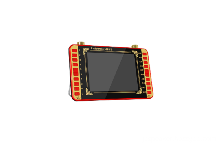
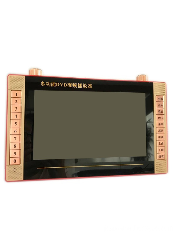
This Portable Video Player is the updated
version of traditional DVD Players.
This Andriod Wifi Video Player breaks
through the traditional design, it has small and light appearance, HD screen,
you can play DVD disk with this Mini
Portable Video Player directly, no need to connect TV again. Besides, this Online Video Player built in USB and TF
Card Jack, you can download your favorite movies, music, TV Plays in these
storage device, and watch them anywhere and anytime you like. We configure big re-chargeable battery
in this Streaming Media Player, have
this Portable DVD players, you will never feel alone during long road trips
and travel.
Portable Video Player,Video Projector Shenzhen New Wonderful Technology Co., Ltd. , https://www.sznewwonderful.com
2 Device hardware circuit design 
Due to factors such as internal and external noise and 50 Hz power frequency interference, even if the circuit has a high common mode rejection ratio, the pulse signal is very weak, which is submerged in the disturbance signal. Since the main peak frequency of the pulse signal is about 1 Hz, the energy component It is also below 20 Hz, so the upper cut-off frequency of the low-pass filter is 40 Hz. For power frequency interference, a symmetrical double-T RC active wave trap is used to filter it out. After the integration and comparison circuit shaping, the standard 0 ~ 5 V pulse signal required by the single chip microcomputer can be obtained. The filter, notch circuit and integral comparison circuit are shown in Figure 3. 
2. 2 single-chip microcomputer control and display circuit 
3 Software design 
4 Circuit debugging and noise analysis 

Design scheme of intelligent human heart rate detection device
Design scheme of intelligent human heart rate detection device0 Introduction