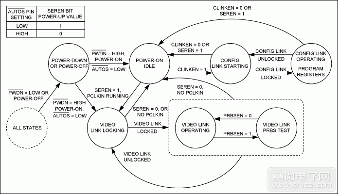
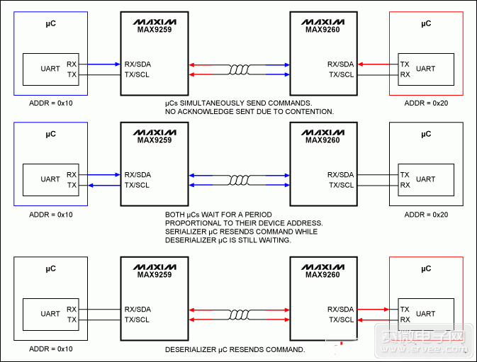
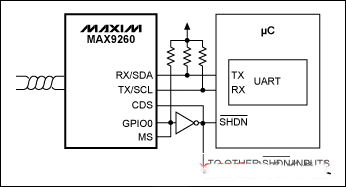
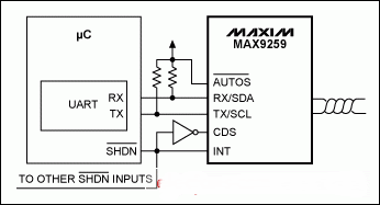
Maxim's Gigabit (Gigabit) Multimedia Serial Link (GMSL) solution converts digital video and audio data serially and then serially over a pair of twisted pairs. In addition, the integrated bidirectional control channel enables a single microprocessor (μC) to program the serializer, deserializer, and all connected peripherals. This article refers to the address: http:// Remote microprocessors and related devices such as clock sources/crystals and low voltage supplies can be eliminated in typical applications. This solution not only simplifies the remote design, but also reduces system cost, size, and power consumption. However, in some cases, considering the special requirements other than GMSL, the system still has μC at both ends of the link. This application note describes how to connect two μCs to control GMSL. Dual μC application basis When using a single μC, if the μC is on the serializer side, the direction selector pin (CDS) at both ends of the serializer/deserializer is normally set low; if μC is on the side of the deserializer, the direction is controlled. Select to be set high. However, if the serializer's CDS is set low and the deserializer's CDS is set high, each GMSL chip can be simultaneously connected to its corresponding μC (Figure 1). Figure 1. Simple dual μC application schematic, CDS setup as shown Internal operation When two μCs are used, both the serializer and the deserializer's I2C master are disabled, and RX/SDA and TX/SDL are configured as their UART interfaces by their corresponding μCs. Since each device operates as a local device, it cannot enter a sleep state. Figure 2. Serializer state diagram (CDS = low) Figure 3. Deserializer state diagram (CDS = high) Each device is brought into a low power state with a corresponding active low PWDN pin. Remember that all device settings are reset to their initial power-on values ​​when waking up from the power-down state. Conflicts in dual μC applications In the configuration shown in Figure 1, each μC can communicate with the MAX9259 serializer, the MAX9260 deserializer, or other μC in accordance with the GMSL UART protocol. GMSL does not provide anti-collision measures, and users need to provide conflict resolution measures. Independent networking The easiest way to prevent collisions is to have each μC set the FWDCCEN and REVCCEN bits of its attached serializer/deserializer to 0 (0x04 D[1:0]). This scheme disables the receivers and transmitters of the forward and reverse control channels and effectively separates the control network into two separate networks (Figure 4). Figure 4. Independent control network avoids the possibility of conflict Any communication over the serial link first requires the μC on each side to re-enable communication for the corresponding link. This setup is very effective in "normal" applications where the settings of critical link-specific registers do not change from the initial state. Software conflict handling In applications where there must be communication between serial links at both ends, users can avoid collisions through higher layer protocols (Figure 5). In the following example, each μC waits for an ACK frame to determine if its instruction was successful. Figure 5. Example of software processing conflicts The serializer/deserializer does not issue an ACK frame when a collision occurs. After receiving an ACK frame, the μC waits for a period of time based on their device address before resending the instruction. Because of this design, the microprocessor has different device addresses and there is no conflict when retrying communication. Single/double μC application Some applications do not require two μCs to always work. During operation, if the CDS input on either end changes state, the corresponding device will resume operation in accordance with the link startup procedure described in the MAX9259 data sheet. Switching between single μC and dual μC operation as needed, taking turns to enable GMSL takes up less resources. The unused μC can be turned off to reduce power consumption and help extend battery life. Remote display example (deserializer) In the following application, the deserializer side of the link is a display panel configured for remote power on/off. Both the board shutdown input and the single/dual μC control are connected to the output of the MAX9260 GPIO0 (Figure 6). Figure 6. Single/double μC remote display example Once powered up, the GPIO outputs a high level to keep the remote device off, and the deserializer is configured as a remote device due to the additional inverter. Since the MS is connected to the GPIO, the MAX9260 powers up in Sleep mode and all other devices are in a low-power state. To turn on the remote panel, the serializer wakes up the MAX9260 and establishes a serial link. Then, the μC of the serializer terminal sets GPIO0 low to make MS low and the inverter output high. The inverter sets the MAX9260 as a local device and wakes up other circuitry on the remote display panel. MS must be asserted low to maintain the basic mode of the MAX9260 UART interface. To turn off the remote panel, the serializer sets GPIO0 high to turn off the remote device and place the MAX9260 as a remote device. Then, set SLEEP = 1 in the MAX9260 to put the device into sleep mode. Remote camera example (serializer) Similar to the above example, the serializer side of the link is a camera module configured to be turned on/off by the remote power source. The MAX9259's INT output controls the board's shutdown input and single/double μC switching (Figure 7). Figure 7. Single/Dual μC Remote Camera Example In this application, INT is used as a GPO, and the output is controlled by setting SETINT (0x0D D7 of MAX9259) or the INT input of the deserializer. Once powered up, the INT output is low, keeping the remote device off. The inverter output is connected to the CDS and the serializer is configured as a remote device. Because the active-low AUTOS is asserted high, the MAX9259 powers up in Sleep mode. To enable the remote panel, the deserializer wakes up the MAX9259 with the GMSL UART command. The deserializer then sets the MAX9259's INT output high to power up all remote devices. The inverter output places the MAX9259 as a local device that accepts UART commands via the local μC. To turn off the far-end panel, the deserializer sets the INT output of the MAX9259 low, turning off the far-end device and setting the MAX9259 as a remote device. The deserializer then sets SLEEP = 1 in the MAX9259 to put the device to sleep. Other applications Dual μC applications are not limited to the above examples. Symmetric, bi-directional control panel with a wide range of serializer/deserializer and μC configurations with real-time CDS and bypass settings (via MS). Designers need higher control to increase system power and minimize system power consumption, maximizing the use of existing resources. Shandong Qingguo Optical Fiber Co., Ltd. , https://www.qgfiber.com


