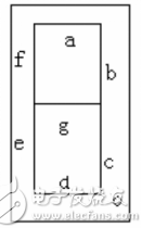
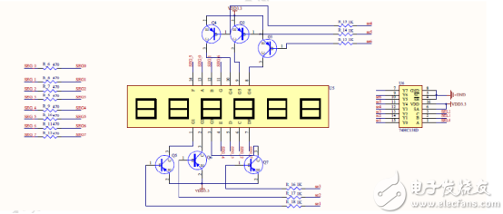
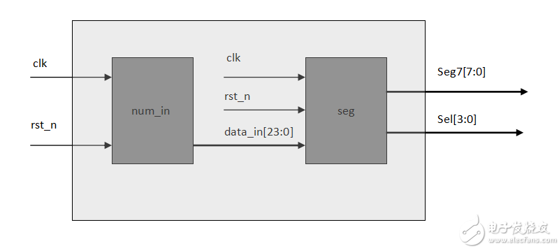
design background: The nixie tube is a semiconductor light-emitting device , and its basic unit is a light-emitting diode. Nixie tubes are used in many of our designs. The simple display principle and clear display effect of nixie tubes have been widely used in our industry. The application of nixie tube is very extensive, involving many fields, we take digital display instrument in this field. Digital display instrument is the abbreviation of digital display instrument. The commonly used displays are LED and LCD as display elements.  Design principle :      This design is to design a display module of digital tube, and the design principle diagram is as follows:     Nixie tube display is divided into dynamic and static display. In order to let people see the nixie tube display, we generally drive the frequency of the nixie tube between 1K-10K. As the name implies, a seven-segment digital tube uses seven segments of lighted lines to spell common numbers and certain letters. This display method is very easy to see in digital circuits. Coupled with the decimal point displayed in the lower right corner, a display unit actually includes 8 signal lines. Depending on the circuit design, these signal lines may be highly effective or inefficient. We control the lighting of these line segments through the FPGA to achieve the display effect. For the display modules of multiple digital tubes, connecting each pin to the FPGA pin consumes a large amount of FPGA pin resources. Therefore, we also introduce a scanning method similar to the matrix keyboard. At any time, we only use 8 signals to light a nixie tube, but the 8 nixie tubes are lit alternately with the clock pace. As long as the clock is fast enough, we observe that the nixie tubes are like several lights at the same time. Our development board uses a dynamic display to cycle through the display. The schematic diagram is as follows:     As shown in the figure, our development board uses six common anode digital tubes, and six PNP type transistors are used as input switches for six groups of digital tube power supplies, which is what we often say as bit selection signals. PNP transistors are low-power. Flat conduction, so our bit selection signal is low and effective. Here, in order to save the IO resources of FPGA, we connected the six bit select signals to the 38HC138D decoder. From the hardware schematic of our board, we can see that our digital tube is red anode, that is, to give a low level is to light a segment of the digital tube, then all 8 segments are given to 8 ' b0000000. This is the number 8, we use a circular display, which is selected through the sel pin which digital tube is bright, that is to say , when the three digits of our sel is 3 ' b000, it is the first digital light, 3 ' b001 The second nixie tube lights up and so on.  Design architecture diagram : Design code : Top-level module 0  module seg_x ( clk , rst_n , sel , seg7 );  // Top port 1  input clk ; // input 2  input rst_n ; 3  output   [ 2 : 0 ] sel ; // output 4  output  [ 7 : 0 ] seg7 ; 5  6  wire  [ 23 : 0 ] num ; 7  8  num_in num_in ( // Instantiate the input module 9  . clk ( clk ), 10. Rst_n (rst_n), 11. Num (num) 12 ); 13 14 seg seg ( // Instantiate the digital tube module 15. Clk (clk), 16. Rst_n (rst_n), 17. Sel (sel), 18. Seg7 (seg7), 19. Data_in (num) 20 ); twenty one  endmodule   Design module 0   module seg ( clk , rst_n , sel , seg7 , data_in );  // Port definition 1   2   input clk ; 3   input rst_n ; 4   input  [ 23 : 0 ] data_in ;    // Enter data for 6 lights 5   6   output  reg  [ 2 : 0 ] sel ;   7   output  reg  [ 7 : 0 ] seg7 ; 8   9   parameter s0 =  3'b000 ; 10  parameter s1 =  3'b001 ; 11  parameter s2 =  3'b010 ; 12  parameter s3 =  3'b011 ; 13  parameter s4 =  3'b100 ; 14  parameter s5 =  3'b101 ; 15  16  `define T1ms 50_000  // Define the count value of 1k 17  // `define T1ms 5 18  reg  [ 15 : 0 ] count ; 19  wire flag ; 20  always  @  ( posedge clk or  negedge rst_n ) twenty one  if (! rst_n ) twenty two  begin twenty three  count  15'b0 ; twenty four  end 25  else 26  if ( count ==  `T1ms  -  1 )   // Count to 1MS 27  begin 28  count  15'b0 ; 29  end 30  else 31  begin 32  count count +  1'b1 ; 33  end 34  35  assign flag = ( count ==  `T1ms   -  1 )  ?  1'b1  :  1'b0 ;  // Flag assignment 36  37  reg  [ 2 : 0 ] state ;  38  reg  [ 3 : 0 ] num ; 39  always  @  ( posedge clk or  negedge rst_n ) 40  if (! rst_n ) 41  begin 42  sel  3'b0 ; 43  state  3'b0 ; 44  num  4'b0 ; 45  end 46  else 47  begin 48  case  ( state ) 49  s0 : begin 50  if ( flag ) 51  state s1 ;    // first lamp lit, to the 4-bit data 24 52  else 53  begin 54  sel  3'b000Axial Metallized Polypropylene Film Capacitors Power Supply Capacitor,Filter Power Capacitor,Hv Film Capacitor,High Voltage Metallized Film Capacitor XIAN STATE IMPORT & EXPORT CORP. , https://www.shvcomponents.com

