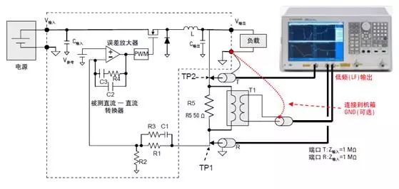
Power integrity measurement objects and measurement content PI (Power Integrity), that is, power integrity, previously belonged to the topic of signal integrity analysis, but because PI is complex and critical enough, it has now been taken out separately as a topic to study. Fast and accurate simulation of power integrity is still a difficult problem to be broken. For high-speed digital circuits and systems, PI's research object is PDN (Power Distribution Network). Taking a notebook computer as an example, the AC to DC power adapter supplies the computer motherboard with a DC power supply of about 16V. The power distribution network on the motherboard should change this 16V DC power supply to a DC power supply of various voltages (eg: + -5V, + 1.5V, + 1.8V, + 1.2V, etc.), power the CPU and power the chips. The power consumption of the CPU and IC is large, and the power consumption is dynamic. The instantaneous current may be large or small, but the voltage must be stable (that is, the ripple and noise must be small) to maintain the normal operation of the CPU and IC . This puts forward strict requirements for PDN. To measure PDN performance, you first need to test the power supply ripple and noise of the CPU and IC pins with an oscilloscope. However, to accurately measure the performance of PDN, you also need to test the output impedance of PDN (impedance that changes with frequency) and the transmission impedance of PDN (also impedance that changes with frequency), just like characterizing a single-port network or dual-port network PDN. Since the current PDN is mostly a switching power supply structure, it is also necessary to measure the loop gain of the PDN or key DC to DC conversion device. To summarize, the power integrity measurement object is the power distribution network PDN. The main measurement content includes four parts: Ripple and noise measurement; Measurement of output impedance; Loop gain measurement; Measurement of performance parameters of filter devices (capacitors / magnetic beads, etc.). Power supply ripple and noise measurement Today's electronic circuits (such as mobile phones, servers, etc.) have higher switching speeds and signal slew rates than before, while chip packaging and signal swing are getting smaller and smaller, making them more sensitive to noise. Therefore, circuit designers today are more concerned about the effects of power supply noise than before. Real-time oscilloscopes are a common tool used for power supply noise measurement, but if used incorrectly, it may bring completely wrong measurement results. Because the power supply noise bandwidth is very wide, many people will choose an oscilloscope for power supply noise measurement. However, it cannot be ignored that real-time broadband digital oscilloscopes and their probes have their own inherent noise. If the noise to be measured is on the same order as the noise of the oscilloscope and probe, it will be very difficult to make accurate measurements. The main noise of the oscilloscope comes from two aspects: the noise of the oscilloscope and the noise of the probe. All real-time oscilloscopes use attenuators and amplifiers to adjust the vertical range. After setting the attenuation, the noise of the oscilloscope will be amplified. For example, when the attenuator is not used, the basic range of the oscilloscope is 5mV / div. Assume that the noise floor of the oscilloscope at this time is 500uVRMS. When the range is changed to 50mV / div, the oscilloscope will add a 10: 1 attenuator to the input circuit. In order to display the correct voltage signal, the oscilloscope will amplify the signal by 10 times when it is displayed last. Therefore, the noise floor of the oscilloscope seems to have 5mVRMS at this time. Therefore, when measuring noise, the most sensitive range file of the oscilloscope should be used as much as possible. However, the oscilloscope usually does not have sufficient offset range in the most sensitive file to pull the measured DC voltage to the center of the oscilloscope screen for testing. Therefore, it is usually necessary to use the AC coupling function of the oscilloscope to filter the DC level and measure only the AC component. Now there are 12bits oscilloscopes on the market, such as Agilent 9000H series oscilloscopes, the noise is relatively small, only 0.7v@100mv/div, so 12bits oscilloscopes are the best choice. For the same reason, the 1: 1 probe should be used as much as possible in the power supply measurement instead of the 10: 1 probe standard with the oscilloscope. Otherwise, the noise of the oscilloscope will be amplified. The noise brought by the probe is coupled in front of the attenuator, so no matter how much the attenuation ratio is set, the noise contributed by the probe is constant. However, under certain incorrect usage methods, the probe may bring additional noise. A typical example is the use of long ground wires. In order to facilitate testing, the passive probe of the oscilloscope usually uses a long ground wire in the form of an alligator clip of about 15 cm, but this is not suitable for power ripple testing, especially in the presence of switching power supplies on the board. Since the switching of the switching power supply will generate a large amount of electromagnetic radiation in the space, and the long ground wire of the oscilloscope probe is exactly equivalent to an antenna, it will introduce large electromagnetic interference from the space into the measurement circuit. A simple verification method is to connect the ground wire and the probe tip together. Close to the circuit under test (without direct contact), you may see relatively large switching noise on the oscilloscope. Therefore, the shortest possible ground wire should be used during the measurement. Many DUTs now require measuring a few millivolts of peak-to-peak ripple and noise. For example, some SerDes above 10Gbps require a 3mv peak-to-peak power supply ripple and noise. At this time, it is best to use a coaxial cable for measurement. Although the impedance of the coaxial cable is only 50 ohms, for the power supply under the milli-even level, the load has little effect and the test accuracy is very high. However, when using a coaxial cable and the oscilloscope is set to a 50-ohm input impedance, the oscilloscope is DC coupled. At this time, there are two processing methods: First, place a capacitor at the contact point of the power supply under test. The capacitor is in contact with the coaxial cable while being connected to the device under test. Generally 0.1uF can be used for the capacitor. Second, make power supply test probes. It is best to make a small PCB with SMA connectors on both ends of the PCB, with the middle exposed, which can be used to place capacitors. Figure 3 is an example of a homemade probe. The last point to note is that the power supply test usually specifies the ripple and noise in a certain frequency range, such as within 20MHz, and the bandwidth of the general oscilloscope is greater than this requirement, so the oscilloscope bandwidth limitation function can be turned on during the test This will also have a better effect on reducing high frequency noise. To summarize, for the test of power supply ripple noise, it is usually necessary to pay attention to the following points: Try to use homemade power test probes Try to use 12bits oscilloscope Try to use the most sensitive range file of the oscilloscope; Try to use AC coupling function; Try to use a probe with a small attenuation ratio; The ground wire of the probe should be as short as possible; Use the bandwidth limitation function as needed; PDN output impedance measurement To measure the performance of PDN, it is not enough to test the power ripple and noise of the CPU and IC pins with an oscilloscope, and there is no way to locate the problem after the problem occurs. To accurately measure the performance of PDN, you also need to test the output impedance of PDN (impedance that changes with frequency) and the transmission impedance of PDN (also impedance that changes with frequency), just like characterizing a single-port network or dual-port network to characterize PDN . This requires the use of network analyzer tools. There are two major challenges to using a network analyzer to test PDN: 1. The output impedance and transmission impedance of the PDN are of the Hoho level (generally around 2m ohms). It is a difficult thing to accurately test. 2. PDN works with DC voltage, that is, with offset, which requires the network analyzer to have the function of offset measurement. To test milliohm output impedance with a network analyzer, one-port test method cannot be used simply because the impedance is too small and the reflection is too large. The better method at this time is to use the dual-port test method, and use S21 instead of S11 during the test. Assuming that the inductance of the probe cable is about 0, Z (DUT) is much smaller than Zo (VNA port impedance), the calculation formula of the PDN output impedance is as follows: ZDUT = Z11 = S21x25 Using a network analyzer to test milliohm output impedance is also a two-port test method. Assuming that the inductance of the probe cable is about 0, Z11, Z21, Z22 are much smaller than Zo, the calculation formula of PDN transmission impedance is as follows: Z21 = Z12 = S21x25 Circuit board system level PDN measurement How to detect? To perform PDN measurements at the circuit board system level, it is best to use SMA connectors or semi-rigid SMA coaxial cables. The signal pin is in the middle of the SMA connector, and the four pins around are the ground pins. You need to use pliers to cut off the three pins and leave one. The semi-rigid SMA cable needs to be cut off to reveal the signal pin in the middle, and the shielded welding short wire is wrapped for ground connection. When probing, try not to probe on the same surface, because the magnetic field generated by the current loop will cause the probes to couple with each other, causing errors. If you can only detect on one side, try to use a short-pin probe made with semi-rigid SMA cable. If you do not need to perform measurements below the kHz level, and you can use the core on the connection cable, we can use the S-parameter port and simple configuration of the E5061B VNA to perform up to PDN impedance on the unpowered or powered system circuit board. 3 GHz measurement. If we need to measure a relatively low frequency response, we can use the instrument's gain-phase test port to measure in the frequency range of 5 Hz to 30 MHz. In the application of system circuit boards, the high DC loop gain of the DC-DC converter maintains a very low low-frequency impedance value at the connection point of its sensing line. When away from the sensing point, the horizontal resistance will increase the low frequency value. This is not a measurement error, but the actual characteristics of the system circuit board PDN. DC-DC converter loop gain measurement GALOCE weight indicators are available in a variety of materials ranging from aluminum to 304 stainless steel enclosures and come with a variety of display options ranging from LCD, LED to large displays and wireless options. output RS232/RS485, can conntact the computer. Optional wall mount kit, stainless steel bracket. Weight Indicator,Digital Load Cell Indicator,Indicator Load Cell, load cell display GALOCE (XI'AN) M&C TECHNOLOGY CO., LTD. , https://www.galoce-meas.com