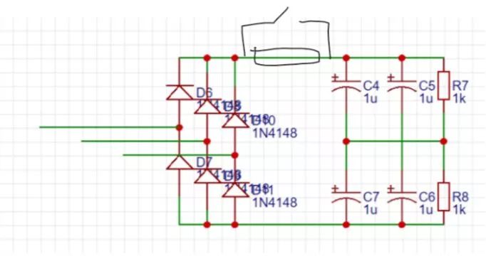
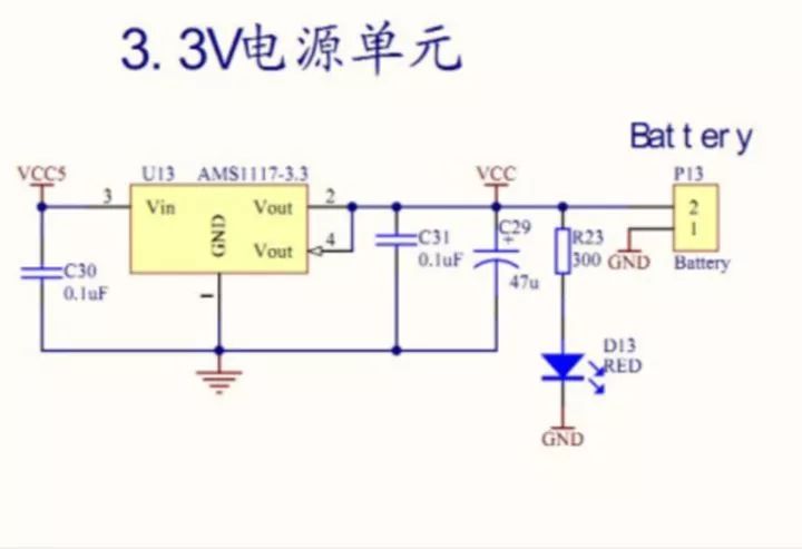
I recently learned a new microcontroller, and found that the circuit diagrams that I am currently exposed to and the circuit diagrams that I read when reading a book are not quite the same. The physical circuit diagram always uses two lines to indicate the power supply and the flow direction is obvious. Now the circuit diagram that comes into contact with, the power is all VCC, the negative is GND, the flow is not clear, do not know from which line to flow out. Checking on the Internet is all about physics circuit diagrams. What is the circuit diagram with VCC and GND? In what book can you learn this foundation? Nowadays, there is a problem in the teaching of domestic mode teaching: it is never said how the various formulas on classical physics become independent components. This has caused many college physics students to find it difficult to model electricity. They cannot interpret the circuit diagrams in reality using the various complicated formulas studied by the University. Second, the university’s analog power is divorced from reality, and the circuitry on the book looks incredibly pure. It can be analyzed to work flawlessly, but the actual effect is often unsatisfactory. Take the switching power supply that universities have been trying to achieve, many books don't add common-mode filters, and often because the EMI generated by LC resonance flows into the circuit through the ground, it will not work properly, even if it is added, the time of interpretation It is generally said that "the impact of reducing grid instability". Or three-phase electric rectification without anti-shock resistance, the first six diodes will all explode on power-on, and even if the anti-shock resistance is added, the circuit of the short-circuit resistance is not added. The boss sees you live. Wasting so much power is sure to open you up. (meaning, do not care about numerical values) First answer the questions in the questions first. Like the main contact MCU control circuit, the contacted GND is usually the signal ground, VCC is also generally 3.3V or 5V, the use of power or battery power. All GNDs are connected together and eventually return to the negative side of the power supply. The same is true of all VCCs, and it is back to the positive electrode of the battery. The AMS1117-3.3 is a chip IC that is commonly used in microcontroller power supplies and converts 5V to 3.3V. VCC5 and the general ground symbol (inverted triangle) come from a 5V supply. C30 is connected to VCC5. Between ground symbols, it has a filtering effect. VCC5 is connected to Vin of the AMS1117 and provides the operating voltage. The ground symbol is connected to the GND of the IC. C31 functions to increase the stability factor. Since the voltage across the capacitor cannot be changed, it is assumed that the power consumption of the microcontroller increases briefly. We do not want this signal to affect the output voltage of the AMS1117 because the AMS1117 has a certain response time. Without this capacitor, the IC will continue to output high voltage or low voltage due to small fluctuations. The unstable power supply will still cause great damage to the microcontroller. With the addition of C31, fluctuations can be reduced due to the energy storage properties of the capacitors. There is another VCC on the right side. We can judge that the voltage on the wire connected to this VCC is 3.3V. C29 is an electrolytic capacitor, which plays a role in energy storage. The GND at the bottom right is the working place of the SCM. The 3.3V voltage from VCC passes through R23 and LED D13, which acts as a power indicator. The battery on the far right is not difficult to see. Pin 2 corresponds to the positive pole of the battery - 3.3V, while pin 1 corresponds to the negative pole of the battery - 0V. When there is no external power supply, 2 (positive battery) - R23 - D13 - GND - 1 (battery negative) constitute a loop, making D13 play a role in indicating the battery power. The VCC representing 3.3V here seems to have no effect, but if VCC is reappeared in the same schematic, such as on a microcontroller, we know that this VCC represents 3.3V, and when the schematic is converted into a circuit diagram, the computer It automatically connects these same symbols. Finally, the battery must also form a circuit to charge, so it is not difficult to think that GND and ground symbols must also be connected together somewhere in the schematic. In fact, in such a circuit, VCC and GND are just a sign, which means that they are connected together. When designing a schematic, it is easy to read, it is easy to find the position of each module, and it can no longer be like a book. Pull the last lead to the end. Then there is the problem of learning. College textbooks are not systematic. It is difficult for people of different abilities to find books of the corresponding level. After reading a book, they do not know which book to read, even if they find two books. There may be different places. Therefore, I recommend that the head teacher do a good job of the relationship with the university teachers, especially those who have work experience, so that they can bring you more, so that you can understand the problems that can not be encountered in the various books that you will encounter in the work. For how to learn electronic circuit knowledge, I can tell the subject of the following points: 1: Make full use of basic physical formulas and laws. Formulas and laws can never be wrong, and any waveform, current, or voltage change can be explained with basic knowledge. Why does the MOS switch have a delay? Because the MOS tube's principle and structure lead to the presence of capacitance inside it. Why the voltage of the ground wire is not 0? Because the ground wire also has a certain resistance. Why do the transistors saturate? Because both PN junctions are forward biased, IC is not controlled by IB. Take root and try to use the formula to explain every phenomenon. 2: Look more, analyze the circuit diagrams. The most convenient way is to search for circuit diagrams on Baidu and look at them one by one, enough for you to see the day. Then we must pay attention to error correction, to see if the use of components and values ​​are correct, there are many things online is wrong. 3: The idea directly into the schematic, the schematic directly into the circuit board. Now playing board is a lot cheaper than before, 10 double-sided looks like seventy to eighty, and also a few meals. Many students obsessed with the circuit every day until they realized that there was a problem. There were also problems, and some seniors still played bread every day. They couldn't even hold the soldering iron. Even if the board is abolished, you can analyze it on the oscilloscope and study the problem. 4: Multi-purpose simulation software. For example, Multisim, the effect of simulation is no less than the effect of a real circuit, a component usually has 30-40 different parameters, and it is more convenient than reality, and the measured value is more arbitrary. In the end, it is still necessary to find a good teacher. Several years of work experience can be summed up for you to listen to, and don’t look at university textbooks anymore. Go straight to the project. With the project you will know what you want to learn and more. It is easy to see the problem.
A new rule from the Drug Enforcement Administration (DEA) threatens to upend the American hemp industry, and could even result in criminal prosecutions for manufacturers of CBD and delta-8 THC products.
The DEA says the [interim final rule," issued Aug. 20, is simply a matter of adjusting its own regulations to account for changes to the Controlled Substances Act that were mandated by the 2018 Farm Bill (or Agricultural Improvement Act) that legalized hemp and CBD production. The new rule [merely conforms DEA`s regulations to the statutory amendments to the CSA that have already taken effect," says the agency. The new rule doesn`t break any ground, according to the DEA.
But many experts on cannabis and hemp law say the DEA rule creates a potential pathway the law enforcement agency could use to prosecute hemp processors and producers of CBD (cannabidiol) and delta-8 THC (or Δ8THC) products. There are two issues: partially processed CBD, and [synthetically derived" delta-8 THC.
Cbd Pod System Oem,Cbd Vape Pod Oem,Best Cbd Pod System,Cbd Pod System Shenzhen MASON VAP Technology Co., Ltd. , https://www.cbdvapefactory.com