Single Phase Portable EV Charger Single Phase Portable Ev Charger,Portable Electric Car Charger,Portable Electric Vehicle Charger,Portable Ev Car Charger Yangzhou JERI New Energy Co., Ltd. , https://www.jrevcharging.com
Circuit Operation Principle The industrial instrumentation sound and light alarm circuit consists of +l2V voltage regulator circuit, switch control circuit, oscillator, flip-flop and sound and light alarm circuit, as shown in Figure 8-120. 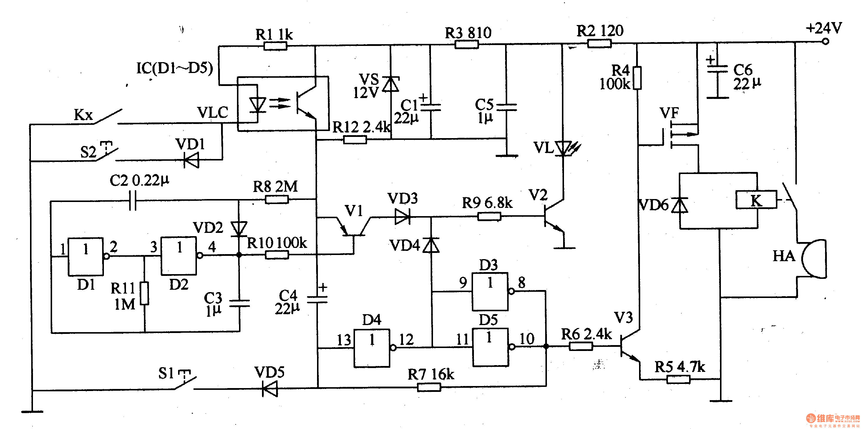
The +l2V regulator circuit consists of resistors R2, R3, filter capacitors Cl, C5, C6 and Zener diode VS.
The switch control circuit consists of resistors Rl, Rl2, goose fitting VLC and industrial instrument control contacts (controlled electrical contacts) Kx.
The oscillator is composed of Dl, D2 and diode VD2, resistor R11, and capacitors C2 and C3 inside the non-gate integrated circuit IC (Dl-D5).
The flip-flop is composed of D3-D5 and resistor R7 inside the lC.
The sound and light alarm circuit is composed of transistors Vl-V3, resistors R4-R6, Rg, R10, LED VL, diodes VD3, VD4, VD6, field effect transistor VF, relay K and alarm HA.
Normally, Kx is in the off state, the LEDs and phototransistors inside the VLC are in the off state, the IC and Vl have no +l2V working voltage, and the audible and visual alarms do not work.
When K, when the instrument's control signal or monitoring parameter exceeds the limit, the VLC is turned on, providing the IC with +l2V working voltage, the oscillator is energized, and the output oscillating signal is amplified by Vl and V2, and the driving VL flashes. Glowing. At the same time, the +l2V voltage of the VLC output is also added to the large end of D4, causing its flip-flop to flip to another state. Both D3 and D5 output a high level, which makes V3 and VF turn on. K is energized and sucked, and its normally open contact is bought and connected, and the HA sounds an alarm.
When the audible alarm release button S1 is pressed, VD5 is turned on, D4 outputs a high level, D5 and D3 output a low level, V3 and VF are turned off, K is released, and HA stops sounding.
S2 is a test button for checking whether the working state of the sound and light alarm is normal. After pressing S2, it is equivalent to Kx being turned on.
Component selection
Rl and R4-Rl2 select 1/4W metal membrane resistor or carbon membrane resistor for use; R2 and R3 select 1/2W metal membrane resistor for use.
Both Cl and C4 are aluminum electrolytic capacitors with a withstand voltage of 16V; C2, C3 and C5 are all monolithic capacitors; C6 is an aluminum electrolytic capacitor with a withstand voltage of 35V or higher.
VDl-VD6 selects 1N4148 type silicon switch diode for use.
VL can be composed of multiple φ5mm red or green high-brightness LEDs (multiple parallel connected and then connected in series).
Vl selects Sg012 or 3CG2l silicon PNP transistor; V2 and V3 select 58050 or 59013 silicon NPN transistor.
VF selects 2SJ135 type field effect transistor.
IC selects CD4069 or MCl4069 type six non-gate integrated circuits.
VLC uses TIL117 or 4N25 optical coupler.
K selects 24V DC relay.
The HA uses an AC 220V bell or a dedicated alarm.
Both S1 and S2 use the micro-motion button.