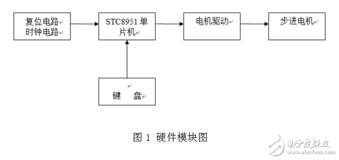
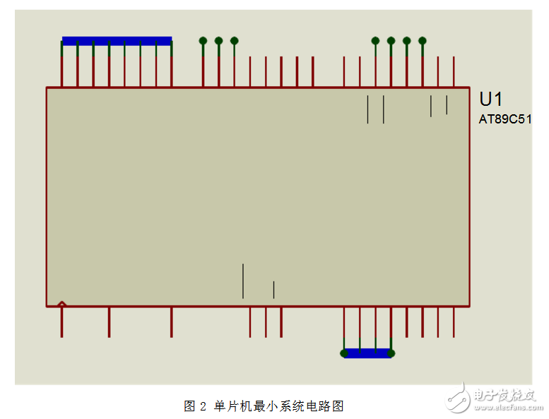
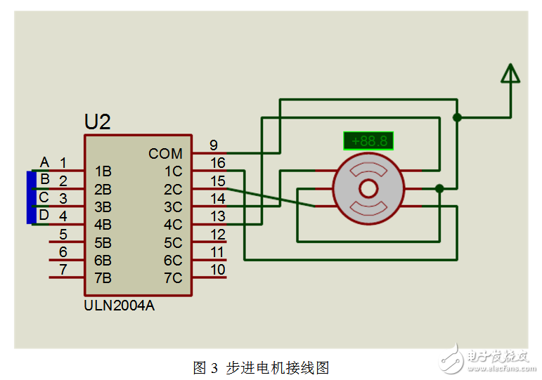
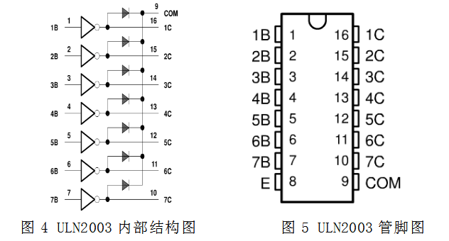
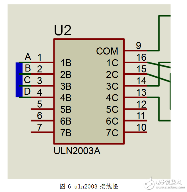
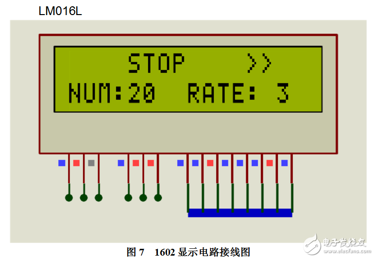
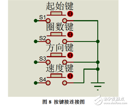
Stepper motors are widely used in various fields of production practice. Its largest application is in the manufacture of CNC machine tools. Because the stepper motor does not require A/D conversion, it can directly convert the digital pulse signal into angular displacement, so it is considered to be the ideal actuator for CNC machine tools. This design uses the proteus simulation software to simulate the circuit. The system controls the start and stop, number of turns, direction, and speed of the motor without setting the four buttons. The above parameters are displayed using 1602 liquid crystal. The whole system has the advantages of good stability, strong practicability and friendly operation interface. A stepping motor is an actuator that converts an electrical pulse into an angular displacement. The angular displacement can be controlled by controlling the number of pulses. Stepper motors are widely used in various fields of production practice. Its largest application is in the manufacture of CNC machine tools. Because the stepper motor does not require A/D conversion, it can directly convert the digital pulse signal into angular displacement, so it is considered to be the ideal actuator for CNC machine tools. Proteus ISIS is a circuit analysis and physical simulation software developed by Labcenter UK. It runs on the Windows operating system and can emulate and analyze (SPICE) various analog devices and integrated circuits. The software features: 1 realizes the combination of single chip simulation and SPICE circuit simulation. System simulation with analog circuit simulation, digital circuit simulation, microcontroller and its peripheral circuits, RS232 dynamic simulation, I2C debugger, SPI debugger, keyboard and LCD system simulation; there are various virtual instruments, such as oscilloscope, logic Analyzer, signal generator, etc. 2 Support the simulation of mainstream microcontroller systems. Currently supported microcontroller types are: 68000 series, 8051 series, AVR series, PIC12 series, PIC16 series, PIC18 series, Z80 series, HC11 series and various peripheral chips. 3 provides software debugging capabilities. In the hardware simulation system, there are debugging functions such as full speed, single step, setting breakpoints, etc., and the current state of each variable, register, etc. can be observed. Therefore, in the software simulation system, these functions must also be provided; and third-party software is also supported. Compile and debug environments such as Keil C51 uVision2. 4 has a powerful schematic drawing function. In short, the software is a simulation software that integrates single-chip microcomputer and SPICE analysis. It is extremely powerful. As shown in the figure below, the whole design is centered on STC89C51 single-chip microcomputer, which consists of reset circuit, clock circuit, motor drive, stepper motor, display circuit, etc. The hardware module is shown in Figure 2-1: The corresponding parameter setting is performed by pressing the button. After receiving the signal, the MCU judges to drive the motor drive module, then the drive circuit drives the stepper motor to run, and uses 1602 to display the set parameters. According to the requirements of the topic, the main control unit uses the C51 microcontroller to control the whole system. STC89C51RC includes 512 bytes of RAM, 32 I/O lines, three 16-bit timer/counters, 8-input 4-priority nested interrupt structure, and one serial I/O port (can be used for multi-machine communication, I/ O-extended or full-duplex UART) as well as on-chip oscillator and clock circuitry. In addition, due to the static design of the device, it provides a wide operating frequency range (frequency can be reduced to zero). Two power-saving modes, idle mode, and power-down mode selected by software are implemented. Idle mode freezes the CPU, but RAM, timers, serial ports, and interrupt systems still work. The power-down mode saves the contents of the RAM, but freezes the oscillator, causing all other on-chip functions to stop working. Since the design is static, the clock can be stopped without losing user data. The run can be resumed from where the clock stopped. Therefore, the microcontroller can meet the system requirements, the circuit diagram is as follows: A stepper motor is an electromechanical component that converts an electrical pulse signal into angular displacement or linear displacement. It is actually a single-phase or multi-phase synchronous motor. The single-phase stepping motor has a single electric pulse drive, and the output power is generally small, and its use is a small power drive. The multi-phase stepping motor has a multi-phase square wave pulse drive and is widely used. This design uses a four-phase three-stepping stepper motor. The connection diagram is as follows: Driver Module We use the integrated driver chip ULN2003, which gives the chip a high withstand voltage, high current Darlington tube consisting of seven silicon NPN Darlington tubes. The characteristics of this circuit are as follows: Each pair of Darlington in ULN2003 is connected in series with a 2.7K base resistor. It can be directly connected to TTL and CMOS circuits at 5V operating voltage, and can directly handle the standard logic buffers that are needed. Processed data. ULN2003 has a high operating voltage, high operating current, sink current up to 500mA, and can withstand 50V in the off state. The output can also run in parallel at high load currents. 1 pin input, 16 pin output, your load is connected between VCC and 16 feet, no 9 feet. ULN2003 is a high-current drive array, which is mostly used in control circuits such as single-chip microcomputers, smart meters, PLCs, and digital output cards. It can directly drive loads such as relays. Therefore, it is enough to meet the requirements of driving stepper motors. The connection diagram is as follows: The LCD display module is constructed by using an LCD display, a background light source, a circuit board, and a driver integrated circuit as one unit as a single component, leaving only one interface for external communication. The display module receives the displayed commands and data through this interface, and displays them according to the requirements of the instructions and data. The external circuit reads out the working status and display data of the display module through this interface. The character generation memory (CGROM) inside the 1602 liquid crystal module has stored 160 different dot matrix character graphics. These characters are: Arabic numerals, uppercase and lowercase letters of English letters, commonly used symbols and Japanese kana characters, etc., each character has 1 fixed code. The user can write the appropriate control commands to the module to complete the operations of clearing the screen, displaying, and setting the address. The design adopts parallel mode control, and the communication interface circuit of LCD and single chip microcomputer adopts direct connection method as shown in FIG. In the design, the keyboard uses a free-standing button structure in a non-encoded keyboard system. The keyboard works in a timed manner. The timer TO timing is used to identify the working state of the button by outputting data. The keyboard is mainly used to provide human-machine interface. The circuit is shown in Figure 3. The independent button circuit is used. Each button switch adopts a pull-up resistor to ensure that each I/O has a certain high level when the button is disconnected. The button function is defined as follows: When P3.2 is pressed, the stepping motor starts to accelerate; when P3.3 is pressed, the stepping motor starts to decelerate; when P3.4 is pressed, the stepping motor starts to rotate forward; when P3 is pressed; When the .5 is pressed, the stepper motor starts to reverse. The elimination of button jitter is achieved by software debounce. The connection diagram is as follows:
ZGAR PCC KIT
ZGAR electronic cigarette uses high-tech R&D, food grade disposable pod device and high-quality raw material. All package designs are Original IP. Our designer team is from Hong Kong. We have very high requirements for product quality, flavors taste and packaging design. The E-liquid is imported, materials are food grade, and assembly plant is medical-grade dust-free workshops.
From production to packaging, the whole system of tracking, efficient and orderly process, achieving daily efficient output. We pay attention to the details of each process control. The first class dust-free production workshop has passed the GMP food and drug production standard certification, ensuring quality and safety. We choose the products with a traceability system, which can not only effectively track and trace all kinds of data, but also ensure good product quality.
We offer best price, high quality Vape Device, E-Cigarette Vape Pen, Disposable Device Vape,Vape Pen Atomizer, Electronic cigarette to all over the world.
Much Better Vaping Experience!
ZGAR PCC KIT E-Cigarette Vape Pen,ZGAR PCC KIT Disposable Device Vape,PCC SET,ZGAR PCC KIT Vape Pen Atomizer,ZGAR PCC KIT Disposable E-Cigarette OEM vape pen,ZGAR PCC KIT electronic cigarette ZGAR INTERNATIONAL(HK)CO., LIMITED , https://www.zgarecigarette.com