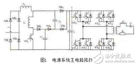
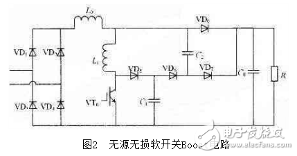
The Boost circuit has been matured in power factor correction. For power factor correction of several hundred watts of low power, conventional circuits are achievable. However, for high power such as induction heating power supplies, there are still many practical problems. In order to solve the situation that the switching device is easily damaged due to the inrush current generated when the diode is reversely recovered, the switching loss of the switching device at a high frequency is reduced. This paper replaces the traditional LC filter circuit with a passive lossless buffer circuit. After analyzing the working principle of the soft-switching circuit and the time-sharing-phase shifting power control strategy of the inverter module, the simulation is carried out by Matlab software, and the correctness of the theoretical analysis is verified by the experimental results. As shown in Figure 1, the main circuit topology is mainly composed of rectification, soft switching Boost power factor correction, inverter, and load matching. The DC voltage output from the single-phase rectifier bridge is connected to the passive buffer soft switch Boost circuit. This paper adopts the Boost circuit to replace the traditional LC filter circuit. Here, the Boost circuit mainly has two functions: one is to increase the power factor of the rectifier input side; the other is to provide a stable DC voltage for the inverter side. The Boost correction circuit outputs a DC voltage to the inverter bridge. The inverter bridge is a single-phase full-bridge inverter composed of 8 IGBT modules. Each IGBT has an anti-parallel diode connected in parallel with it as the inverter voltage. Continue to flow. The power device in the inverter is driven by the control circuit to control the pulse signal and periodically switch; the function of the isolation transformer T is electrical isolation and impedance matching of the load. Generally, T is a step-down transformer. By appropriately changing the transformer ratio, the voltage on the inductor and capacitor in the resonant tank can be reduced, and different load impedance matching can be performed. The output square wave voltage is isolated and stepped down by the transformer and applied to the resonant circuit composed of the compensation capacitor and the induction coil and the load. 1.1 Soft Switch APFC Circuit Working Principle Figure 2 shows the passive soft-switch Boost circuit, series inductor and lossless SNUBBER circuit. Compared with the ordinary Boost circuit, increasing the inductance L1 limits the VT0 turn-on surge current due to the reverse recovery of VD0, C2→VD7 as the SNUBBER circuit of VD0, the series structure of VD5→VD6→VD7 and L1→C1→C2 The resonance and energy conversion between the two is also beneficial to suppress the opening surge current of VT0. The operation of the main circuit in one cycle can be divided into six stages: (1) Mode 1 [t0, t1]: At time t0, C0 is discharged through the resistor R, VT0 is turned on in the ZCS state, C1 is discharged, and current flows through the C1 → C2 → L1 loop. Due to the action of L1, the turn-on current of VT0 Gradually rising steadily. (2) Mode 2 [t1, t2]: The current on the inductor L1 gradually increases. After the discharge of C1 is completed, the current flows through the loop L0 → L1 → VD5 → VD6 → C2. (3) Mode 3 [t2, t3]: C2 is slowly charged until all L1 energy is transferred. Finally, the current flowing through VT0 is equal to the size of L0, and C2 charging ends. (4) Mode 4 [t3, t4]: At time t4, VT0 is turned off in ZVS. When the voltage of C2-VD6-C1 and the rectified output voltage Vin are equal, C2 is discharged through VD7, and the current of L1 is passed through L0→L1→ VD5→C1 charges C1.
Gas Turbine Flowmeter is a new generation of high-precision and high-reliability gas precision metering instrument that integrates temperature, pressure, flow sensor and intelligent flow totalizer through optimized design based on advanced technology of flow meter at home and abroad and integrated theories of gas mechanics, fluid mechanics and electromagnetics.
Gas Turbine Flow Meter,Intelligent Turbine Flowmeter,Air Turbine Flow Meter,Natural Gas Turbine Flow Meter Kaifeng Chuangxin Measurement & Control Instrument Co., Ltd. , https://www.kfcxflowmeter.com