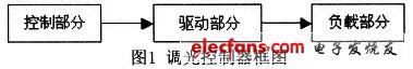
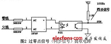
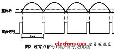
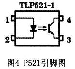
1 dimming controller design In daily life, we often need to adjust the brightness of the light. The dimming controller realizes the adjustment of the brightness of the incandescent lamp (pure resistive load) by controlling the conduction of the bidirectional thyristor through the single chip microcomputer. The characteristics of the triac are that it will remain on even after the turn-off signal is turned off after the turn-on; when the load current is zero (the AC voltage cross-zero), it will automatically turn off. Therefore, it is necessary to send a trigger signal during each half-wave of the alternating current, and the timing of the trigger signal determines the brightness of the bulb. The implementation of dimming is to trigger the turn-on of the triac after a period of zero-crossing. The longer this period, the shorter the time that the thyristor is turned on, the lower the brightness of the lamp; otherwise, the more the lamp bright. This requires extracting the zero-crossing point of the AC voltage, and based on this, determines the sending time of the trigger signal to achieve the purpose of dimming. 1.1 Hardware Part The block diagram of this dimming controller is as follows: Control part: In order to facilitate flexible design, select programmable devices that can be written multiple times. Here, ATMEL's AT89C51 single-chip microcomputer is selected. Drive section: Since it is driven by AC, it can be driven by relay or optocoupler + thyristor (thyristor SCR). Due to the mechanical action, the relay has a slow response and cannot meet its needs. The thyristor can realize the non-contact control of the alternating current in the circuit, control the large current with a small current, and has no spark generated when the control is like the relay, and the action is fast, the service life is long, and the reliability is high. So here is the choice of thyristor. Load section: This circuit can only control the brightness of incandescent lamps (pure resistance load). 1.2 Software Section The object to be controlled is a 50Hz sinusoidal alternating current. The signal of the zero-crossing point (synchronization signal) is taken out by the optocoupler, and this signal is sent to the external interrupt of the single-chip microcomputer. After receiving the synchronization signal, the single-chip microcomputer starts a delay program, delaying The specific time is changed by the button. When the delay ends, the microcontroller generates a trigger signal, through which the thyristor is turned on, and the current flows through the thyristor through the incandescent lamp to make the lamp emit light. The longer the delay, the shorter the time of the light, the darker the brightness of the lamp (there is no flickering feeling, because the repetition frequency is 100 Hz, and the human vision has a persistence effect). Since the length of the delay is determined by the button, it is actually the button that controls the intensity of the light. In theory, the delay time should be any value within 0 to 10 ms. In the program, divide a cycle into N equal parts, and each button only needs to change its aliquot. Here, the larger N is better, but it is only required by the limitation of the MCU itself and based on practical necessity. It can be divided into about 100 copies, and the actual value used is 95. The trigger pulse width of the thyristor depends on the specific optocoupler combined with the oscilloscope observation, taking 20 μs in this design. T1 is used in the program to control this time. There are two ways to handle two dimming buttons: one is to adjust one step (light or dark) regardless of the time of each button; the other is that the adjustment method is different depending on the button time: Short press to adjust only one step, long press to adjust continuously. As mentioned above, since the number of steps in this design is 95 (N=95), if the former method is used, the operation is too troublesome, so it is more reasonable to use the latter. 2 unit circuit and description 2.1 AC voltage zero-crossing signal extraction The AC voltage zero-crossing signal extraction circuit is shown in Figure 2. The synchronization signal in the figure is the AC voltage zero-crossing signal we need. The waveforms of each part are shown in Figure 3. The horizontal dashed line in the rectified waveform in the figure indicates the threshold voltage of the input diode of the aperture P52l. P521 is an abbreviation of TLP521, and the following figure is its pin diagram. The suffix "-1" of the device name in the pin map indicates that a set of pupils is included. Outdoor Led Screen,Outdoor Waterproof Led Screen,Waterproof Led Screen,Outdoor Led Display Screen ALLIN , https://www.nbdisplayapio.com