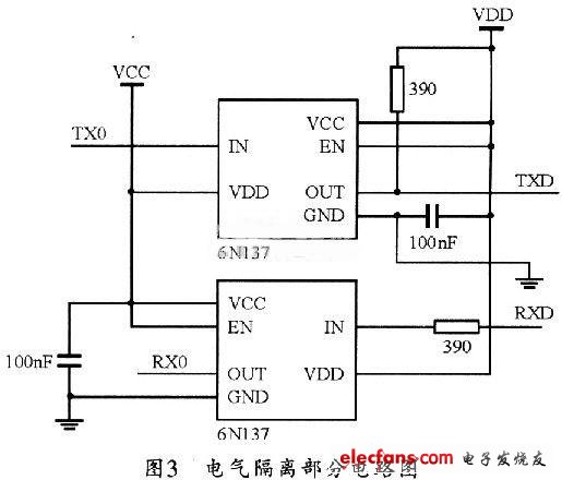
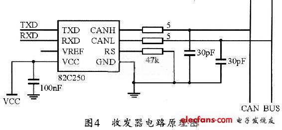
With the continuous improvement of the requirements of the bus on all aspects of the bus, the number of systems on the bus is increasing, and then problems such as increased complexity of the circuit, decreased reliability, and increased costs. In order to solve the above-mentioned problems, the implementation method of CAN bus communication module based on SJAl000 is described in this paper. This method uses PCA82C250 as the bus transceiver of the communication module and SITA-1000 as the network controller. And use STCSTC89C5l one-chip computer to finish CAN communication hardware design based on STC89C5l. The article also designs and analyzes the platform initialization, module sending and receiving. Test and analysis proves that the system can meet the communication requirements of CAN, and the whole system has high practicability. 0 Preface Fieldbus is a bus-type topology network applied at the lowest level of production. It is a communication network that can be used as a field control system to directly connect serially to all controlled device nodes. In terms of industrial automation, the field of its control can range from a home appliance to a workshop or a factory. Under normal circumstances, the environment in which the controlled equipment and the network are located may be very special, and the interference to the signal is often multi-faceted. But the requirement for control must be very real-time, which determines that the field bus is different from the general network characteristics. In addition, because the devices of fieldbus are usually standardized and functionally modular, they also have the characteristics of simple design and easy reconfiguration. 1 CAN bus overview CAN (Controller Area Network) is the controller area network. It was originally designed by the German Bosch company for automotive detection and control systems. Compared with the general communication bus, the data communication of CAN bus has outstanding reliability, real-time and flexibility. Its good performance and unique design make the CAN bus more and more attention. Due to the characteristics of the CAN bus itself, its application range is no longer limited to the automotive industry, but to automatic control, aerospace, nautical, process industry, machinery industry, textile machinery, agricultural machinery, robots, CNC machine tools, medical equipment and sensors And other fields. At present, CAN has formed an international standard, and has been recognized as one of the most promising fieldbuses. Its straight-line communication distance can reach l Mbps / 30m. The number of other nodes depends on the bus driver circuit, which can currently reach 110. 2 CAN system hardware design Figure 1 shows a hardware block diagram of a CAN system based on the CAN2.0B protocol. The system includes a power supply module, an MCU part, a CAN controller, an optocoupler, a CAN transceiver, and an RS232 interface. The hardware system MCU uses STC89C51, the CAN controller uses SJAl000, the CAN transceiver uses PCA82C250, and the optocoupler isolation uses 6N137. The CAN controller SJAl000 in Figure 1 is a replacement for the CAN controller (BasicCAN) PCA82C200. It adds a new operating mode (PeliCAN), which can support many new features of CAN2. OB agreement. The microprocessor STC89C51 can read and write the registers in SJAl000 in a certain mode to control SJAl000 to send and receive data. The CAN transceiver PCA82C250 is the interface between the CAN controller and the physical bus. It was originally designed for high-speed applications (lMbps) in automobiles. The device can provide a difference to the bus Automatic sending and receiving functions. It uses a two-wire differential drive method to help suppress transient interference in harsh electrical environments such as automobiles. PCA82C250 can convert TTL level and CAN bus differential signal from SJAl000 to each other, and can make the bus have better EMC characteristics. Optocoupler isolators can electrically isolate each CAN node on the bus to enhance system reliability and reduce system-to-system interaction. 2.1 Design of CAN controller hardware circuit Connect ADO ~ AD7 of SJAl000 to P0 port of STC89C5l, and CS to P20 of STC89C5l. In this way, when P20 is O, the CPU off-chip memory address can select SJAl000, and the CPU performs corresponding read and write to SJAl000 through these addresses operating. When designing, you can connect the RD, WR, ALE of SJAl000 to the corresponding pins of STC89C51 respectively, and INT connects to IN-T0 of STC89C51, so that the CPU can access SJAl000 by interrupt mode. The connection circuit diagram is shown in Figure 2. 2.2 Design of photoelectric coupler In order to enhance the anti-interference ability of the CAN bus node, TX0 and RX0 of SJAl000 are not directly connected to the TXD and RXD of the transceiver PCA82C250, but are connected to the PCA82C250 through the high-speed optocoupler 6N137, so that each CAN can be well achieved Electrical isolation between nodes. It should be noted that the power supply VCC and VDD used in the optocoupler part are preferably completely isolated, and can be implemented with a low-power power supply isolation module, which can improve the stability and safety of the node. The circuit diagram is shown in Figure 3. 2. 3 CAN transceiver design PCA82C250 is a differential transceiver, it can complete the conversion of TTL level to differential signal. Its CANH and CANL pins are each connected to the CAN bus through a 5 Ω resistor, which can play a certain current limiting role and protect the PCA82C250 from overcurrent impact. CANH and CANL have two small 30pF capacitors in parallel with ground. It can filter high-frequency interference on the bus and has a certain ability to prevent electromagnetic radiation. A slope resistor should be connected to the RS pin of PCA82C250. The size of the resistor can be adjusted appropriately according to the communication speed of the bus. Generally, it can be between 16 and 140 kΩ. Here, a 47 kΩ resistor is selected. Figure 4 shows the circuit diagram of the transceiver. Semi-Round Sensor Automatic Dustbin Stainless Trash Can,Semi-Round Sensor Automatic Dustbin,Semi-Round Series Sensor Dustbin,Semi-Round Sharp Sensor Dustbin NINGBO ZIXING ELECTRONIC CO.,LTD. , https://www.zixingautobin.com