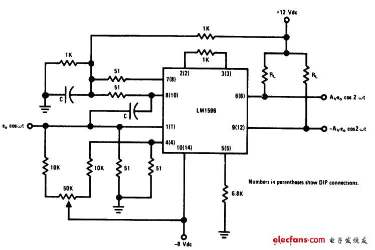
This circuit can be used to amplify low-level signals with slight distortion. The value of C should correspond to the low resistance at the operating frequency. The maximum value of the signal level of the carrier input cannot exceed 25mV, otherwise it cannot work in the linear region of the switching differential amplifier. The highest level of 50mV can be used for some distortion of the output waveform. Broadband frequency doubler circuit: We make OBD connector with terminal by ourselves,
soldering type and crimping type are both available. Also 12V and 24V type. OBD1, OB2, J1939, J1708, J1962, etc. Also molded by different
type, straight type or right-angle type. The OBD connector cables used
for Audi, Honda, Toyota, BWM, etc. We have wide range of materials
source , also we can support customers to make a customized one to
replace the original ones. Vehicle Diagnostic Cables,Diagnostic OBD Cable,OBD2 Splitter Y Cables,OBD2 Diagnostic Adapters,OBD Heavy Vehicle Cables ETOP WIREHARNESS LIMITED , https://www.wireharness-assembling.com