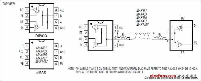
The MAX1487 is a low-power transceiver for RS-485 and RS-422 communication. Each device has a driver and a receiver. The driver slew rate of the MAX1487 is not limited, and it can achieve a transmission rate of up to 2.5Mbps. The MAX1487 transceiver draws a supply current between 120µA and 500µA in the no-load or full-load state where the driver is disabled. All devices work under a single 5V power supply. The driver has a short-circuit current limit, and the driver output can be placed in a high-impedance state through a thermal shutdown circuit to prevent excessive power loss. The receiver input has fail-safe characteristics, when the input is open, it can ensure a logic high output. The input impedance of the receiver with a 1/4 unit load allows up to 128 MAX1487 transceivers on the bus. The MAX1487 is designed for half-duplex applications. The differential balanced system composed of it has strong anti-interference ability. The receiver can detect signals as low as 200mv. It is a high-speed, low-power, easy-to-control asynchronous communication interface chip. MAX1487 pin configuration and typical working circuit chart The pins and internal structure block diagram of MAX1487 are shown in the figure above. Pin 1 RO: receiver output (A―B≥ + 0.2V, RO = “1â€: A―B≤―0.2V, RO = “1â€); Pin 2 RE: receiver enable; Pin 3 DE: drive enable; Pin 4 DI: drive input; Pin 5 GND: ground; Pin 6 A: receiver non-inverting input Or driver non-inverted output; Pin 7 B: receiver inverting input Or the inverting output of the driver; Pin 8 VCC: power supply According to MAXIM, the device features are as follows: 1. Power supply voltage 4.75V≤VCC≤5.25V 2. Supply current 120μA-500μA, quiescent current 230μA 3. Common mode input voltage range ―7V —— + 12V 4. The communication transmission line can hang up to 128 transceivers 5. Transfer rate 2.5MB / S 6. Transmission delay 30ns 7. Jump slope 5 ns 8. Working temperature 0 ° C-+ 70 ° C The input pin DI of the MAX1487 can be directly connected to the TXD pin of the microcontroller CPU, and the output pin RO is connected to the RXD pin of the microcontroller CPU. The driver and receiver inside the MAX1487 are tri-stated, and transmit and receive through DE (driver output high-level enable) and RE (receiver low-level enable). The two control signals of transmit and receive are inverting of. The two can be connected to the same control signal (P3.5 in Figure 2), that is, "1" level controls transmission and "0" level controls reception. A and B terminals realize multi-machine networking. 24V Lithium Battery Charger,Lithium Polymer Battery Charger,24V Bike Lithium Battery Charger,24V Bicycle Lithium Battery Charger Changxing Deli Technology Co., Ltd. , https://www.delipowers.com