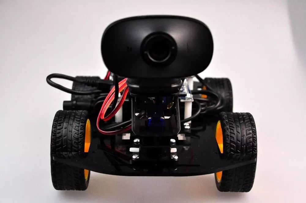
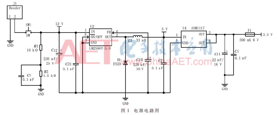
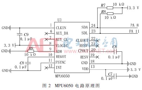
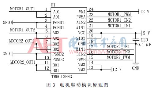
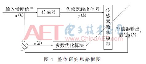
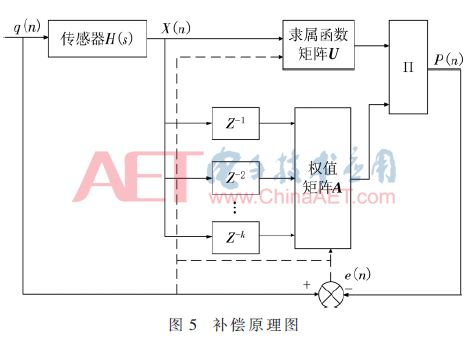
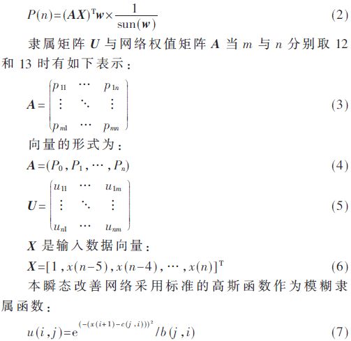
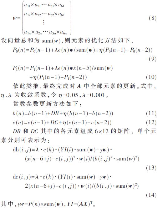
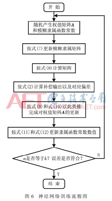
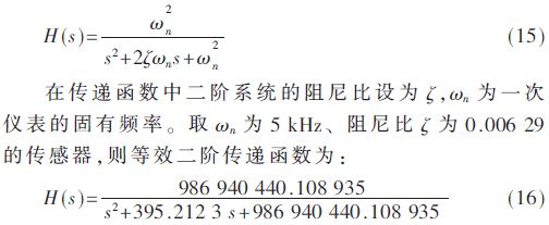
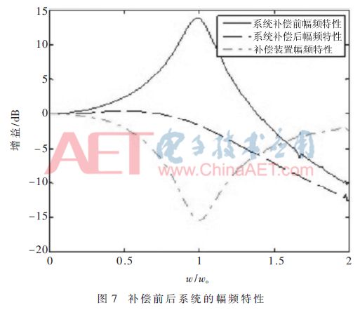
Summary: For the smart car, the transient signal output by the gyro sensor changes very quickly during steering, especially in tight corners. Due to the insufficiency of signal measurement and grasping problems caused by the limitations of its own structure and technology, a STM32 turn control chip is designed. And FPGA is a verification method for the core of a instrument feature improvement unit control core. The test results show that the system can effectively improve the dynamic characteristics under the traditional cornering and improve the accuracy of real-time signal processing under sharp bends after the turn signal acquisition and amplification. 0 Preface The newly released wheeled robot called Handle from Google’s Boston Dynamics Company has been uplifted to a new height. In fact, this smart robot is equipped with a variety of sensor acquisition modules, environmental detection and human-computer interaction modules. Different road conditions result in different curvatures of different curves. How to maintain accurate perception and storage processing in the case of sharp turns has been the focus of research [1]. The turning control of smart cars is a complicated control process. To establish a corresponding mathematical model, simply selecting the classic PID algorithm is not precise enough, and it is difficult to accurately measure and estimate. Therefore, this paper proposes a dynamic test correction module [2-4] after the transfer function. 1 Smart Car Curve Design Background In order to maintain stable, fast, and safe driving under sharp turn conditions, smart cars mainly reflect whether the car can perform monitoring and feedback in real time in motion control. Because the surrounding environment of the car under test is complex and changeable, the lighting conditions, road temperature, relative motion difference caused by its own structure, and friction coefficient will all cause the parameter changes and burrs brought by the smart car and even the detection of blind spots.[5-6 ]. Taking into account the unilateral customization of the control strategy under the turn control of the car, the stability and timeliness of the overall operation process will be biased so as to run off the runway. In response to the complex and ever-changing environment, a reasonable control strategy compensation module is synthesized to make the car In the corner environment, it can not only maintain the reliable and stable signal, but also quickly, efficiently and accurately adjust the posture and control on the bend [7]. 2 system hardware 2.1 The main controller module The main controller used in this system is the STM32F107 embedded chip based on the Cortex-M3 core architecture designed by STMicroelectronics. The chip has the advantages of high performance, low power consumption, real-time application, and high cost performance. The chip embeds 256 KB Flash, 64 KB SRAM, and a variety of peripheral interfaces (I2C, SPI, USART, CAN, USB, timer, DMA controller, ADC, PWM), supports JTAG and SWD debug interface, the highest frequency Up to 72 MHz [8]. The chip's rich on-chip resources and on-chip peripherals, accurate and efficient computing capabilities make it very much in line with system requirements. 2.2 Power Management Module The total power supply for the system is a 12 V lithium battery. The motor drive chip is a TB6612FNG chip. The system voltage is converted to 5 V by the LM2596T switch voltage drop converter. The output of the linear constant voltage module AMS1117 is 3.3 V, converted to 5 by the conversion chip. V and 3.3 V are used by each module of the system. The power circuit diagram is shown in Figure 1. 2.3 Attitude sensor circuit design module The MPU6050 used in this system is a 6-axis sensor chip that integrates a 3-axis gyroscope, a 3-axis accelerometer, and an expandable digital motion processor DMP. Three 16-bit ADC channels measure accelerometers and gyroscopes. The analog signal is converted to a digital signal for output, which guarantees the output accuracy of the measurement data. The user can control the range of the sensor according to actual needs and can accurately track the attitude change of the trolley. The MPU6050 automatically processes accelerometer and gyro data through its own DMP programming, which reduces the computational burden of the main control chip STM32 [9]. The main chip and MPU6050 sensor circuit connection diagram shown in Figure 2, MPU6050 sensor through the transmission rate of the I2C bus and the main chip to communicate. 2.4 Motor Drive Module DC motors have the advantages of large torque, good loadability, fast response speed, smooth motion, and low noise, making DC motors more and more widely used in the field of mobile robots [10-11]. The most common driving method is through Change the period of the pulse sequence and duty cycle to control the motor voltage. The system motor drive chip uses TB6612FNG [12], with dual-channel output, higher efficiency than L298N, lower heat, 4 motor control modes: forward rotation, reverse rotation, braking, stop, output PWM pulse signal through STM32F107 Adjust the motor speed. The schematic diagram of the motor drive module is shown in Figure 3. 3 algorithm optimization Because the system contains a very high frequency component when turning, the signal to be measured changes rapidly. Although the dynamic response of the gyroscope can satisfy rapid changes, it is easy to accumulate errors. If you want to adjust and improve the sensor output signal, you can use the signal processing method in the microprocessor detection system to track the dynamic characteristics of the instrument in real time. In the detection system including the dynamic characteristics cascade improvement module, a signal compensation and correction method is adopted to receive the analog signal output by the sensing end in real time and perform analysis and processing, to extend the amplitude-frequency characteristic effective section of the middle end to a certain extent, and to increase the car system. The effective conditioning rate. Based on the principle of designing a network that can be connected in series with the gyroscope to improve the transient characteristics of the primary instrument, the amplitude-frequency characteristics obtained by the primary instrument matching the improved algorithm network are longer than those of the unprocessed flat segment. The revised thinking is shown in Figure 4. A standard known turning input signal causes spectral output distortion due to insufficient extraction of the effective bandwidth of the gyroscope frequency. For this reason, the measurement and control circuit module increases the deformation signal cascade dynamic characteristics to improve the network, and then optimizes the output through a specific parameter near the primary instrument inverse model. Thus, the offset of the original signal is neutralized for correction purposes. The Laplace transform of the original instrument output cascades with the input Laplace transform ratio H(s) to extend the dynamic characteristic module F(s) of the measurable linear segment. The new transfer function of the module overall is: The principle of compensation is shown in Figure 5. One instrument transient improvement network combines the theoretical input difference e (n) between the fuzzy neural output and the transient calibration signal of a single instrument to achieve fuzzy neural adaptive optimization. The standard primary instrument transient signal is denoted by q(n), the transient output of the primary instrument to be improved is denoted by X(n), and the order of the output of the fuzzy neural network P(n) is set by k, the output is: According to the optimal value obtained by training of the ambiguity function in the upper computer, for the membership function matrix of the fuzzy neural network, k=12, m=12. w is a column vector of matrix U that is combined by elements in U: Figure 6 is a flow chart of a modified compensation network. The most typical instrument is an approximate second-order system whose transfer function can be expressed as: On the MATLAB platform, after training the sensor for 300 times with data, the time domain response before and after the improvement of the dynamic characteristics of the instrument can be obtained. In order to better detect the response output of the instrument on the frequency components of each unit, the tracking and scanning method can be used to obtain the dynamic characteristics of the modules before and after conditioning to obtain the amplitude-frequency characteristics of the system, as shown in Figure 7, where w is the signal under test Frequency, wo is the natural frequency, and the frequency ratio is within 0.3 with good measurement accuracy. 4 Conclusion In this paper, an improved version of the fuzzy adaptive PID control algorithm for intelligent car rapid turning is studied [13]. This algorithm improves the situation where the traditional corners are fast and easy to turn over. The simulation results show that the new algorithm to increase the compensation module can effectively maintain the turning attitude, and the overall accuracy is higher than the traditional single fuzzy PID algorithm. How to further correct minor attitudes is the focus of the next step. Shenzhen Kate Technology Co., Ltd. , https://www.katevape.com