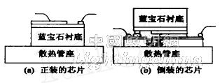
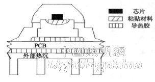
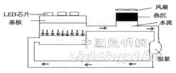
1 Introduction With the rise of GaN-based third-generation semiconductors, the research of blue and white LEDs has been successful, and semiconductor lighting has brought another leap in the history of human lighting. Compared with incandescent and fluorescent lamps, LED has become one of the main development directions of a new generation of environmentally-friendly lighting sources due to its small size, all solid state, long life, environmental protection and power saving. It is also the most promising prospect in the 21st century. One of the high-tech fields. Governments of all countries attach great importance to it and have introduced national plans and invested heavily in development. At the end of the 20th century, LumiledsLighting packaged the first high-power LEDs, which made the LED power jump from tens of milliwatts to more than 1000mW. The luminous flux of a single LED device jumped from less than one lm to more than a dozen lm. At present, high-brightness white LEDs have reached the level of 100 lm/W in the laboratory, and high-power white LEDs of 50 lm/W have also entered commercialization. For W-class (≥1W) high-power LEDs, the current electro-optic conversion efficiency is about 15%, and the remaining 85% is converted into thermal energy, while the chip size is only 1mm × 1mm ~ 25mm × 25mm, which means the power of the chip. The density is very large, how to improve the heat dissipation capability of high-power LEDs is the core problem to be solved in LED device packaging and device application design. 2 The effect of thermal effects on high power LEDs A light emitting diode is an injecting electroluminescent device made of a Group IIIV compound. Under the action of an external electric field, the electro-mechanism caused by the recombination of electrons and holes converts 10% to 15% of the energy into light energy, while the lattice oscillation generated by the non-radiative recombination converts the remaining 85% to 90% of the energy. Converted into heat. Unlike conventional lighting devices, white LEDs do not contain infrared in the luminescence spectrum, so their heat cannot be released by radiation. For a single LED, if the heat is concentrated in a chip of small size and cannot be effectively dissipated, the temperature of the chip is increased, causing a non-uniform distribution of thermal stress, a luminous efficiency of the chip, and a decrease in lasing efficiency of the phosphor. Studies have shown that when the temperature exceeds a certain value, the failure rate of the device will increase exponentially. For every 2 °C rise in component temperature, the reliability will decrease by 10% [3]. In order to ensure the lifetime of the device, the pn junction temperature is generally required to be below 110 °C. As the temperature of the pn junction rises, the wavelength of the white LED device will red-shift. The statistical data show that at a temperature of 100 ° C, the wavelength can be red shifted by 4 to 9 nm, resulting in a decrease in the absorption rate of the YAG phosphor, a decrease in the total luminous intensity, and a deterioration in the white light chromaticity. At around room temperature, for every 1 °C increase in temperature, the luminous intensity of the LED will be reduced by about 1%. When multiple LEDs are densely arranged to form a white light illumination system, the heat dissipation problem is more serious. Therefore, solving the heat dissipation problem has become a prerequisite for power LED applications. 3 package structure and materials For the problem of package heat dissipation of high-power LEDs, designers and manufacturers of devices at home and abroad optimize the design of the thermal system of the device in terms of structure and materials. For example, in the package structure, a large-area chip flip-chip structure, a metal circuit board structure, a heat conduction channel structure, a micro-flow array structure, and the like are used; in the selection of materials, a suitable substrate material and a bonding material are selected, and a silicone resin is used instead. Epoxy resin. In order to solve the problem of package heat dissipation of high-power LEDs, various structures have been developed internationally. 3.1 Package Structure There are currently three main types: 1) Silicon-based flip chip (FCLED) structure. Conventional LEDs have a formal structure with a layer of epoxy on top and sapphire as a substrate. Due to the poor thermal conductivity of epoxy resin, sapphire is a poor conductor of heat, and heat can only be dissipated by the pins under the chip. Therefore, both front and rear sides cause heat dissipation problems, which affect the performance and reliability of the device. In 2001, LumiLeds developed the AIGalnN power flip chip structure. As shown in Figure 1, the LED chip was flip-chip bonded to the silicon substrate. This heat does not have to pass through the sapphire substrate of the chip, but directly to the silicon or ceramic substrate with higher thermal conductivity, and then to the metal base. Since the active heating region is closer to the heat sink, the internal heat sink can be reduced. Thermal resistance [3]. The theoretical calculation of the thermal resistance of this structure can reach a minimum of 134K/W, actually 6~8K/W, and the light extraction rate is also increased by about 60%. However, the thermal resistance is proportional to the thickness of the heat sink. Due to the mechanical strength and thermal conductivity of the silicon wafer, it is difficult to further reduce the thermal resistance of the internal heat sink by thinning the silicon wafer, which further restricts the heat transfer performance. . Figure 1 Comparison of the package structure and flip-chip structure of the chip 2) Based on the metal circuit board structure. The metal circuit board structure utilizes metal such as aluminum to have excellent heat conduction properties, and the chip is packaged on a PCB board covered with a copper electrode of several millimeters thick, or the chip is packaged on a PCB of a metal core, and then packaged to heat dissipation. On-chip to solve the heat problem. UOE's Norlux series of LEDs assembles the packaged products on metal core PCB boards with aluminum interlayers. PCB boards are used for LED device electrode connection wiring, and aluminum core interlayers are used as heat sinks, as shown in Figure 2. Show. Although the structure can obtain good heat dissipation characteristics and greatly increase the input power of the LED, the PCB in the interlayer is a poor conductor of heat, which hinders the conduction of heat. According to research, the thermal resistance of the structural system is between 60 and 70K/W. Figure 2 Metal circuit board structure 3) Micro pump structure. In 2006, ShengLiu et al. solved the problem of heat dissipation of LED by installing a micro-pump system on the heat sink. In the closed system, water enters the small groove of the bottom plate of the LED to absorb heat under the action of micro-pump, and then returns to small In the water container, the heat is absorbed by the fan. This micro-pumped structure (Figure 3) can reduce the external thermal resistance to 0192K/W [6]. The micropump structure has better refrigeration performance, but like the former two structures, if the internal interface has a large thermal resistance, the heat conduction is greatly reduced, and the structure is also complicated. Figure 3 Micro pump structure 3.2 After the packaging material package structure is determined, the thermal resistance of the system can be further reduced by selecting different materials to improve the thermal conductivity of the system. Currently, domestic and foreign materials are often selected for substrate materials, adhesive materials and packaging materials. 1) Substrate material. For high-power LEDs, in order to solve the problem of electrode lead breakage between the chip material and the heat-dissipating material due to thermal expansion mismatch, ceramics, Cu/Mo plates and Cu/W plates can be used as heat-dissipating materials. However, the production cost of these alloys is too high, which is not conducive to large-scale, low-cost production. The use of aluminum and copper plates with good thermal conductivity as the heat sink substrate is one of the current research priorities. 2) Chip bonding material. It is very important to ensure the thermal conductivity of the device by selecting the appropriate chip substrate bonding material and ensuring that the bonding thickness is as small as possible in the mass production process. Bonding is usually carried out using four materials: thermal paste, conductive silver paste, tin paste and gold-tin alloy solder. Thermally conductive adhesives have poor thermal conductivity. Conductive silver paste has good thermal conductivity and good adhesion strength. However, silver paste is not the best choice for pasting materials because it will heat up while raising brightness and contains toxic metals such as lead. Conductive solder paste is similar to silver paste and does not meet ROHS standards due to heavy metals such as lead and hexavalent chromium. Compared with the first three, the thermal conductivity of the gold-tin alloy solder is the best among the four materials, and the electrical conductivity is also excellent, but the rigorous mechanical design is required to achieve high-precision solid crystal. 3) Epoxy resin. Epoxy resin as a packaging material for LED devices has excellent electrical insulation properties, adhesion and dielectric properties, but epoxy resin is hygroscopic, aging, poor heat resistance, easy to change color under high temperature and short-wave illumination, and is cured. There is a certain degree of toxicity before, and the internal stress of curing is large, which has an impact on the life of the LED device. At present, many LED packagers have switched to silicone and ceramic instead of epoxy resin as packaging materials to improve the life of LEDs. In general, the new package structure with low thermal resistance, good heat dissipation and low mechanical stress is the key technology of the package. There are three ways of conducting heat from the junction to the surrounding environment: conduction, convection, and radiation. Different structures and materials need to solve the heat dissipation problems of the following three steps: chip junction to epitaxial layer, epitaxial layer to package substrate, package substrate to cooling device. These three links constitute the channel for the heat conduction of the solid-state lighting source, and any failure of the weak link will destroy the LED light source. In other words, in order to maximize the heat dissipation performance and reliability of power LEDs, materials with high thermal conductivity are required in all three aspects. 4 Conclusion At present, as the brightness of power LEDs increases and the drive current increases, solving the heat dissipation problem has become a prerequisite for the industrialization of high-power LEDs. According to the heat dissipation link of the above LED device, this paper believes that the following aspects can be studied to improve the heat dissipation performance of high power LED. (1) The amount of heat generated by the LED depends on the internal quantum effect. In the growth process of GaN materials, the material structure is improved, the growth parameters are optimized, high-quality epitaxial wafers are obtained, the quantum efficiency in the device is improved, the heat generation is fundamentally reduced, and the heat conduction from the chip junction to the epitaxial layer is accelerated. (2) Select a substrate with a high thermal conductivity such as an Al-based metal core printed circuit board (MCPCB), ceramic, DBC, or composite metal substrate to accelerate heat dissipation from the epitaxial layer to the heat dissipation substrate. A metal-based low-temperature sintered ceramic (LTCCM) substrate is formed by optimizing the thermal design of the MCPCB board or directly bonding the ceramic to the metal substrate to obtain a substrate having good thermal conductivity and a small thermal expansion coefficient. (3) In order to diffuse the heat on the substrate to the surrounding environment more quickly, a metal material with good thermal conductivity such as Al or Cu is usually used as a heat sink, and a forced cooling such as a fan and a loop heat pipe is added. It is not advisable to use an external cooling device for LED lighting, both in terms of cost and appearance. Therefore, according to the law of conservation of energy, using piezoelectric ceramics as a heat sink, converting heat into vibration mode and directly consuming heat energy will become one of the focuses of future research. (4) For high-power LED devices, the total thermal resistance is the sum of the thermal resistance of several heat sinks from the pn junction to the external environment, including the internal heat sink thermal resistance of the LED itself, and the internal heat sink to the PCB board. Between the thermal resistance of the thermal paste, the thermal resistance of the thermal paste between the PCB and the external heat sink, the thermal resistance of the external heat sink, etc., each heat sink in the heat transfer circuit will cause certain obstacles to heat transfer. Therefore, after long-term research, the authors believe that the number of internal heat sink interfaces is reduced, and the necessary interface electrode heat sink and insulation layer are directly fabricated on the metal heat sink by the thin film process, which is greatly reduced by reducing the thermal resistance of the internal heat sink. The amplitude reduces the total thermal resistance, and this technology is likely to become the mainstream of high-power LED thermal packaging in the future. Edit: Cedar Automatic Coffee Maker,Coffee Pod Machines,Pod Coffee Makers,Instant Pod Coffee machine, Ground Coffee and Pod 2 in 1 machnie FOSHAN FORTUNE ELECTRICAL APPLIANCE CO.,LTD , https://www.coffelady.com